


3. SIGNALS AND WIRING
3 - 16
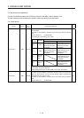
(2) Cable connection procedure
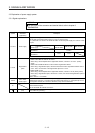
(a) Fabrication on cable insulator
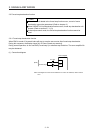
Refer to table 3.1 and 3.2 for stripped length of the cable insulator. The appropriate stripped length
of cables depends on their type, etc. Set the length considering their status.
Insulato
r
Core
Stripped length
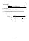
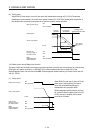
Twist strands lightly and straighten them as follows.
Loose and bent strands Twist and straighten
the strands.
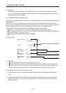
You can also use a ferrule for connection with the connectors. When using a ferrule, select a ferrule
and crimping tool listed in the table below.
Servo amplifier Wire size
Ferrule model (Phoenix Contact)
Crimp terminal
(Phoenix Contact)
For one For two
MR-JE-10B to
MR-JE-100B
AWG 16 AI1.5-10BK AI-TWIN2 × 1.5-10BK
CRIMPFOX-ZA3
AWG 14 AI2.5-10BU
MR-JE-200B to
MR-JE-300B
AWG 16 AI1.5-10BK AI-TWIN2 × 1.5-10BK
AWG 14 AI2.5-10BU AI-TWIN2 × 2.5-10BU
AWG 12 AI4-10GY
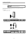
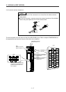
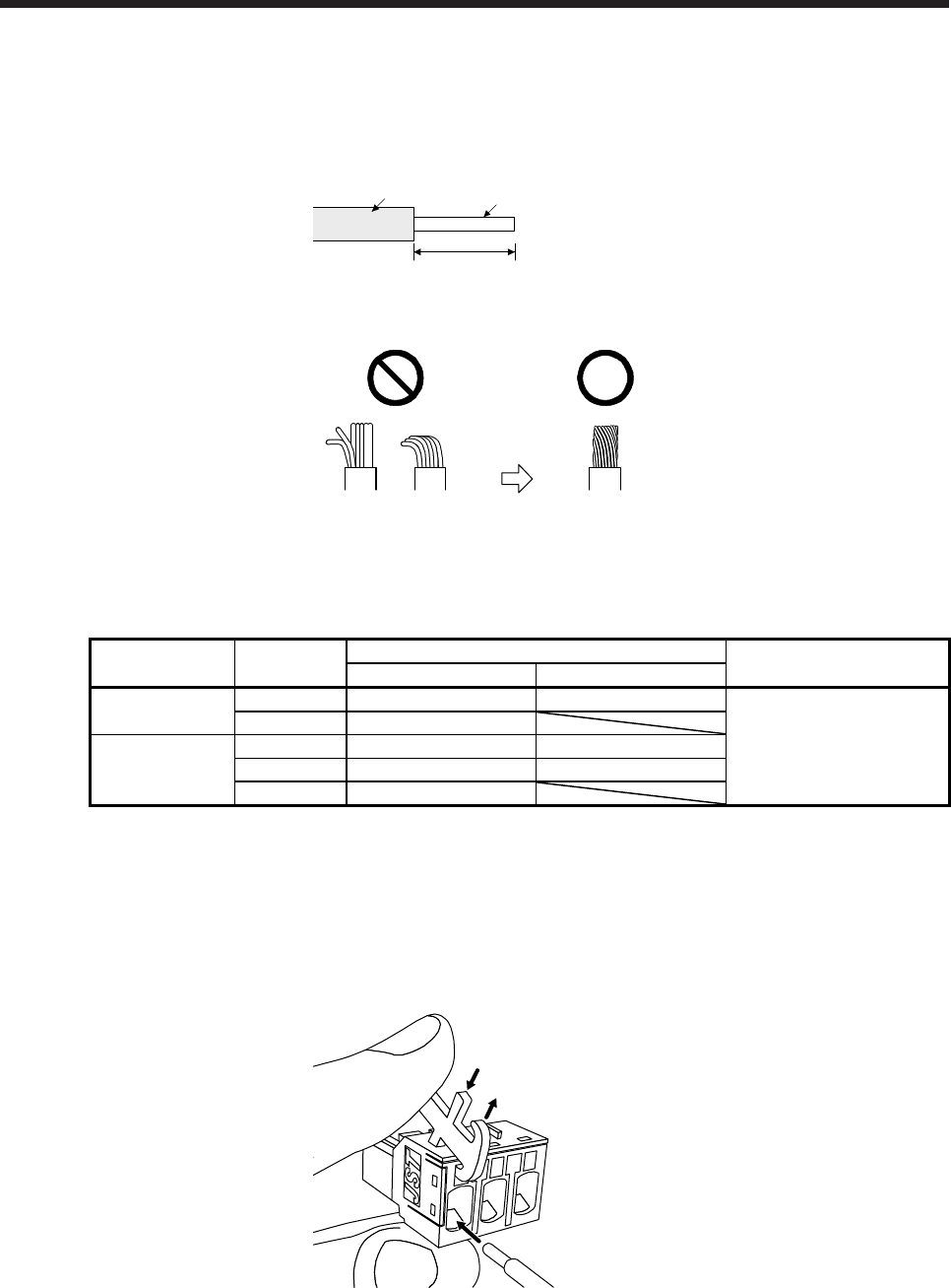
(b) Inserting wire
Insert the open tool as follows and push down it to open the spring. While the open tool is pushed
down, insert the stripped wire into the wire insertion hole. Check the insertion depth so that the wire
insulator does not get caught by the spring.
Release the open tool to fix the wire. Pull the wire lightly to confirm that the wire is surely connected.
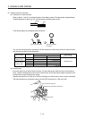
The following shows a connection example of the CNP2 connector for 2 kW and 3 kW.
1) Push down the open tool.
3) Release the open tool to fix the wire.
2) Insert the wire.