


APPENDIX
App. - 9
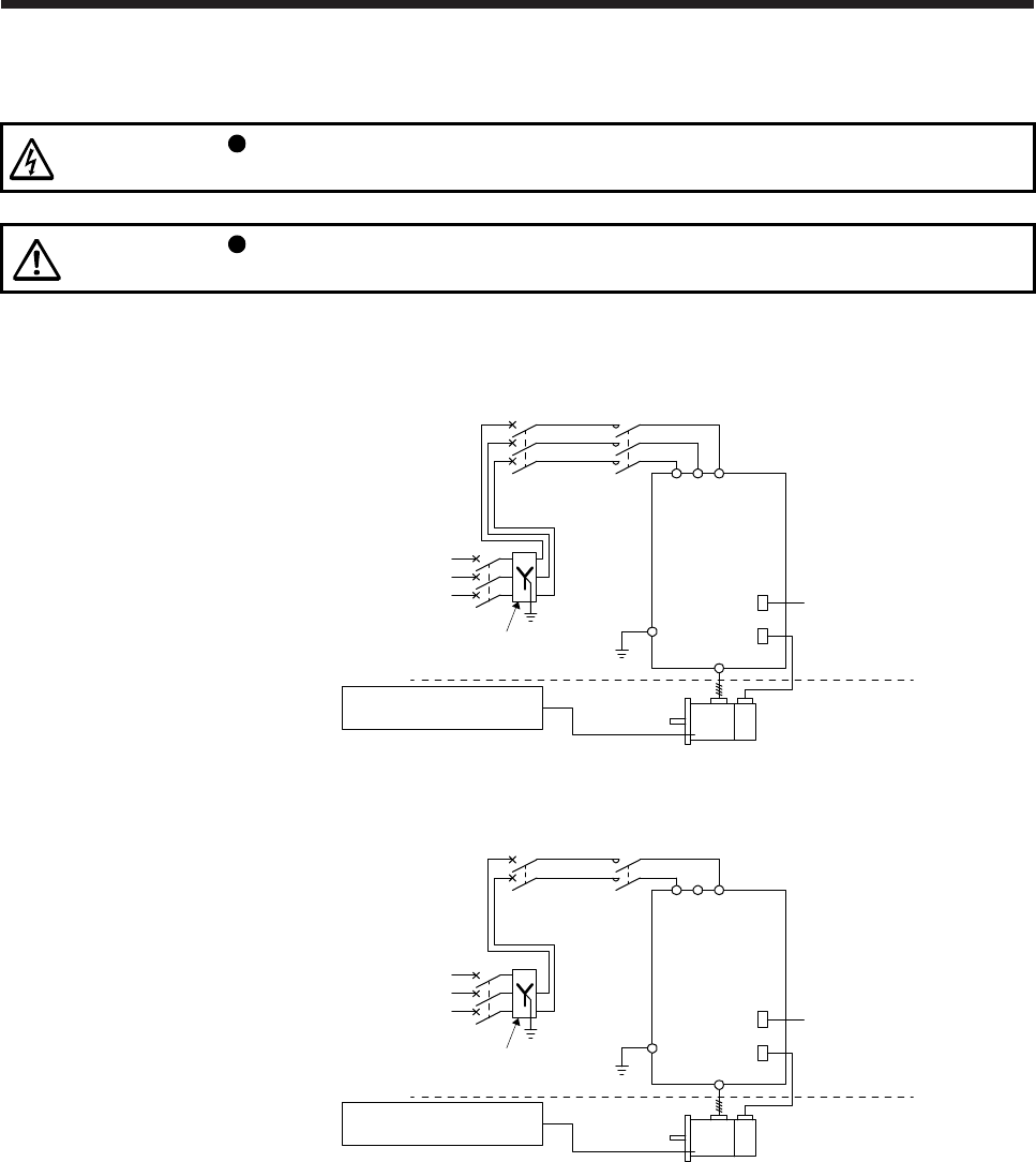
App. 4.3 Electrical Installation and configuration diagram
WARNING
Turn off the molded-case circuit breaker (MCCB) to avoid electrical shocks or
damages to the product before starting the installation or wiring.
CAUTION
Connecting a servo motor for different axis to U, V, W, or CN2 of the servo
amplifier may cause a malfunction.
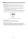
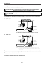
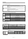
The following shows representative configuration examples to conform to the IEC/EN/UL/CSA standards.
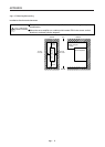
(1) 3-phase input
MCCB
or fuse
Controller
Encoder cable
(3-phase
230 V AC)
Power
supply
(3-phase
400 V AC)
Transformer
(star-connected)
PE
MC
Servo amplifier
Cabinet side
Machine side
Encoder
Servo motor
L1
U/V/W/PE
CN2
CN1
L2L3
To protective equipment
(Thermal signal) (Note)
Note. Please use a thermal sensor, etc. for thermal protection of the servo motor.
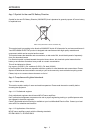
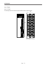
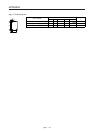
(2) 1-phase input
MCCB
or fuse
Controller
Encoder cable
(1-phase
230 V AC)
Power
supply
(3-phase
400 V AC)
Transformer
(star-connected)
PE
(Note 2)
MC
Servo amplifier
Cabinet side
Machine side
Encoder
Servo motor
L1
U/V/W/PE
CN2
CN1
L2L3
To protective equipment
(Thermal signal) (Note 1)
Note 1.
Please use a thermal sensor, etc. for thermal protection of the servo motor.
2.
For the MR-JE-200_ servo amplifiers, connect the power supply to L1 and L2.
Leave L3 open.
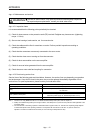
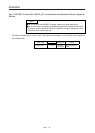
The control circuit connectors described by rectangles are safely separated from the main circuits described
by circles.
The connected motors will be limited as follows.
HG-KN/HG-SN series servo motors (Mfg.: Mitsubishi Electric)