


APPENDIX
App. - 4
App. 4.1.3 Correct use
Always use the MR-JE servo amplifiers within specifications (voltage, temperature, etc. Refer to section 1.3
for details.). Mitsubishi Electric Co. accepts no claims for liability if the equipment is used in any other way or
if modifications are made to the device, even in the context of mounting and installation.
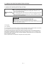
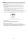
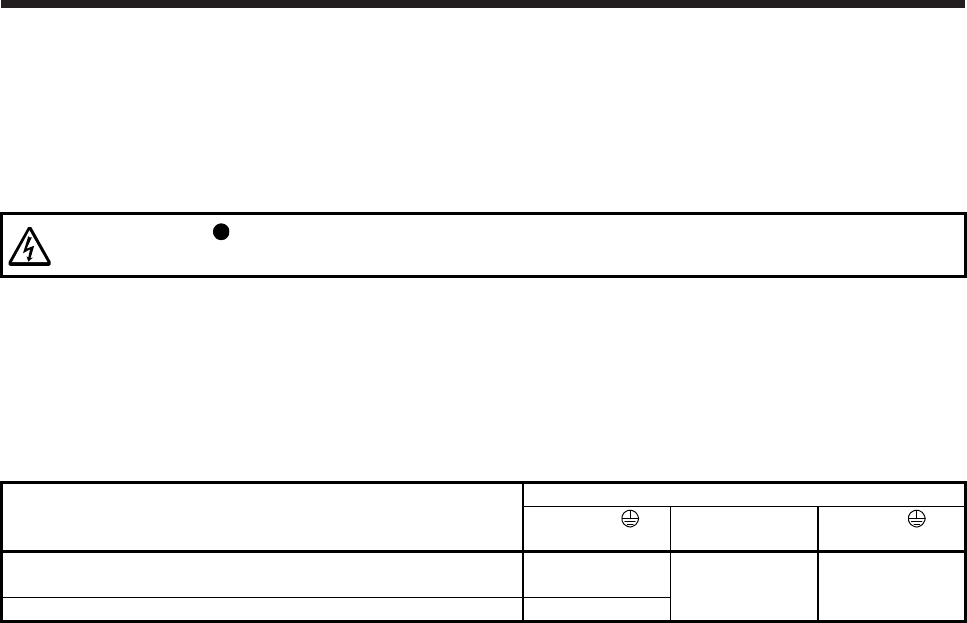
WARNING
It takes 15 minutes for capacitor discharging. Do not touch the unit and terminals
immediately after power off.
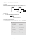
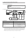
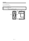
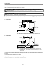
(1) Peripheral device and power wiring
The followings are selected based on IEC/EN 61800-5-1, UL 508C, and CSA C22.2 No.14.
(a) Local wiring
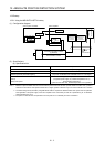
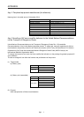
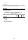
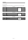
The following table shows the stranded wire sizes [AWG] symbols rated at 75 °C/60 °C.
Table. Recommended wires
Servo amplifier (Note 3)
75 °C/60 °C stranded wire [AWG]
L1/L2/L3/
(Note 2)
P+/C
U/V/W/
(Note 1, 2)
MR-JE-10_/MR-JE-20_/MR-JE-40_/MR-JE-70_/MR-JE-100_ (T)/
MR-JE-200_/MR-JE-300_
14/14
14/14 14/14
MR-JE-200_ (S) 12/12
Note 1. Select wire sizes depending on the rated output of the servo motors. The values in the table are sizes based on rated output of
the servo amplifiers.
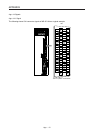
2. The following shows the PE terminal specifications of the servo amplifier.
Screw size: M4
Tightening torque: 1.2 [N•m]
Recommended crimp terminals: R2-4 (Manufactured by JST)
Crimping tool: YPT-60-21 (Manufactured by JST)
3. "(S)" means 1-phase 200 V AC power input and "(T)" means 3-phase 200 V AC power input in the table.