


3. SIGNALS AND WIRING
3 - 2
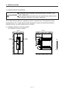
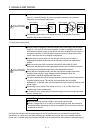
CAUTION
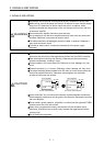
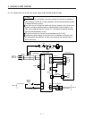
Connect the servo amplifier power output (U, V, and W) to the servo motor power
input (U, V, and W) directly. Do not let a magnetic contactor, etc. intervene.
Otherwise, it may cause a malfunction.
U
Servo motor
M
V
W
U
V
W
U
M
V
W
U
V
W
Servo amplifier
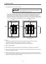
Servo motorServo amplifier
Connecting a servo motor of the wrong axis to U, V, W, or CN2 of the servo
amplifier may cause a malfunction.
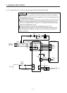
3.1 Input power supply circuit
CAUTION
Always connect a magnetic contactor between the power supply and the power
supply (L1, L2, and L3) of the servo amplifier, in order to configure a circuit that
shuts down the power supply on the side of the servo amplifier’s power supply. If
a magnetic contactor is not connected, continuous flow of a large current may
cause a fire when the servo amplifier malfunctions.
Use an alarm to switch power off. Not doing so may cause a fire when a
regenerative transistor malfunction or the like may overheat the regenerative
resistor.
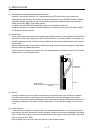
Before removing the CNP1 connector from MR-JE-40B to MR-JE-100B,
disconnect the lead wires of the regenerative resistor from the CNP1 connector.
Not doing so may break the lead wires of the regenerative resistor.
Check the servo amplifier model, and then input proper voltage to the servo
amplifier power supply. If input voltage exceeds the upper limit of the
specification, the servo amplifier will break down.
The servo amplifier has a built-in surge absorber (varistor) to reduce noise and to
suppress lightning surge. The varistor can break down due to its aged
deterioration. To prevent a fire, use a molded-case circuit breaker or fuse for input
power supply.
Connecting a servo motor of the wrong axis to U, V, W, or CN2 of the servo
amplifier may cause a malfunction.
N- terminal is not a neutral point of the power supply. Incorrect wiring may cause
a burst, damage, etc.
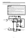
POINT
EM2 has the same function as EM1 in the torque control mode.
When a 1-phase 200 V AC to 240 V AC power supply is used, the connection
destination differs depending on the servo amplifier. Ensure that the connection
destination is correct.
Configure the wiring so that the power supply is shut off and the servo-on command is turned off after
deceleration to a stop due to an alarm occurring, an enabled servo forced stop, or an enabled controller
forced stop. A molded-case circuit breaker (MCCB) must be used with the input cables of the power supply.