


3. SIGNALS AND WIRING
3 - 37
3.10 Servo motor with an electromagnetic brake
3.10.1 Safety precautions
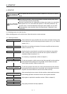
CAUTION
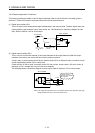
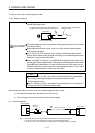
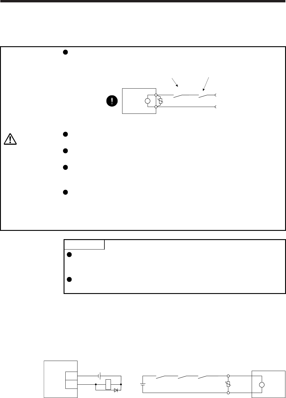
Configure an electromagnetic brake circuit so that it is activated also by an
external EMG stop switch.
Servo motor
Electromagnetic brake
B
U
RA
Contacts must be opened when ALM (Malfunction)
or MBR (Electromagnetic brake interlock) turns off.
24 V DC
Contacts must be opened with the
EMG stop switch.
The electromagnetic brake is provided for holding purpose and must not be used
for ordinary braking.
Before operating the servo motor, be sure to confirm that the electromagnetic
brake operates properly.
Do not use the 24 V DC interface power supply for the electromagnetic brake.
Always use the power supply designed exclusively for the electromagnetic brake.
Otherwise, it may cause a malfunction.
When using EM2 (Forced stop 2), use MBR (Electromagnetic brake interlock) for
operating the electromagnetic brake. Operating the electromagnetic brake without
using MBR during deceleration to a stop will saturate servo motor torques at the
maximum value due to brake torque of the electromagnetic brake. This can result
in delay of the deceleration to a stop from a set value.
POINT
Refer to "HG-KN_/HG-SN_ Servo Motor Instruction Manual" for specifications
such as the power supply capacity and operation delay time of the
electromagnetic brake.
Refer to "HG-KN_/HG-SN_ Servo Motor Instruction Manual" for the selection of
a surge absorber for the electromagnetic brake.
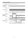
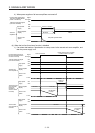
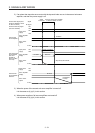
Note the following when the servo motor with an electromagnetic brake is used.
1) The brake will operate when the power (24 V DC) turns off.
2) Turn off the servo-on command after the servo motor stopped.
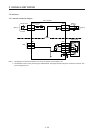
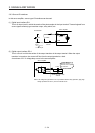
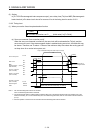
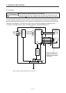
(1) Connection diagram
B2
B1
Servo motor
24 V DC
(Note 3)
Servo amplifier
MBR
DOCOM
MBR
RA1
RA1
U
B
(Note 1)
(Note 2)
24 V DC
Note 1. Create the circuit in order to shut off by interlocking with the emergency stop switch.
2. Do not use the 24 V DC interface power supply for the electromagnetic brake.
3. Create the circuit in order to shut off by interlocking with an alarm detected by the controller.