


3. SIGNALS AND WIRING
3 - 32
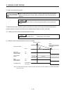
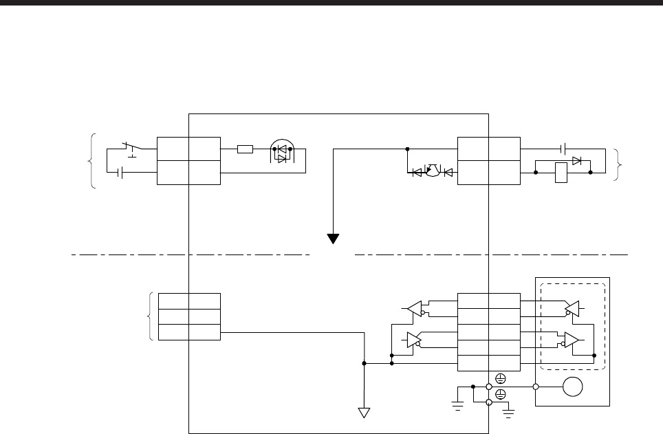
3.8 Interfaces
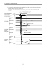
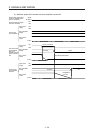
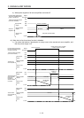
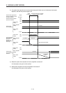
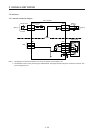
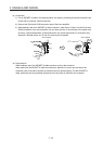
3.8.1 Internal connection diagram
Approximately
6.2 kΩ
Encoder
3
2
4
7
8
MR
MRR
MD
MDR
LG
PE
Servo motor
M
CN2
EM2
CN3
20
10
CN3
3
13
DOCOM
Servo amplifier
(Note 1)
USB
D+
GND
D- 2
3
5
CN5
MBR
DICOM
Forced stop 2
(Note 1)
RA
(Note 2)
24 V DC
(Note 2)
24 V DC
Isolated
Note 1. This diagram is for the sink I/O interface. For source I/O interface, refer to section 3.8.3.
2. The illustration of the 24 V DC power supply is divided between input signal and output signal for convenience. However, they
can be configured by one.