


4. STARTUP
4 - 3
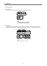
(2) I/O signal wiring
(a) The I/O signals should be connected correctly.
Use the DO forced output to forcibly turn on or off the pins of the CN3 connector. This function can
be used to check the wiring. At this time, check the wiring in the servo-off status.
Refer to section 3.2 for details of I/O signal connection.
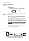
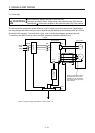
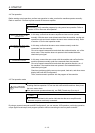
(b) A voltage exceeding 24 V DC is not applied to the pins of the CN3 connector.
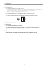
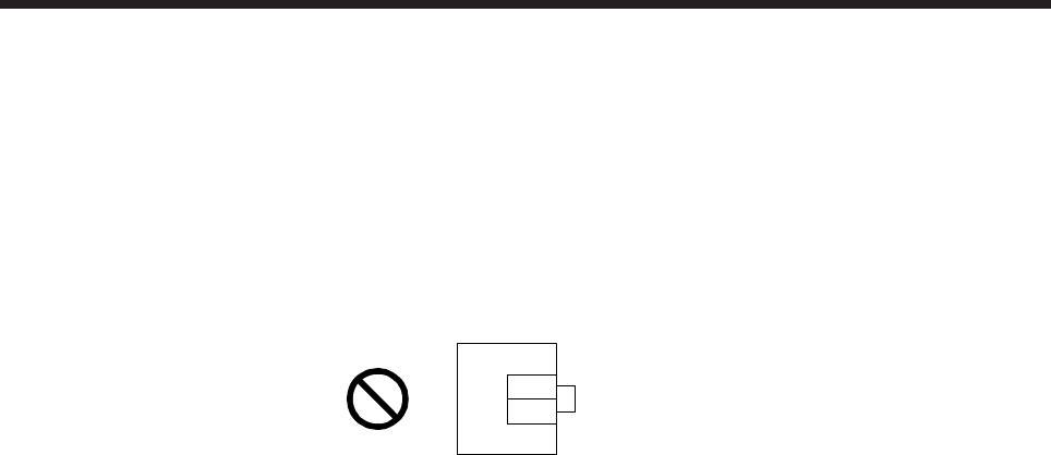
(c) The wire between the plate and DOCOM of the CN3 connector should not be shorted.
Servo amplifier
DOCOM
Plate
CN3
4.1.3 Surrounding environment
(1) Cable routing
(a) The wiring cables should not be stressed.
(b) The encoder cable should not be used in excess of its bending life. (Refer to section 10.4.)
(c) The connector of the servo motor should not be stressed.
(2) Environment
Signal cables and power cables are not shorted by wire offcuts, metallic dust, or the like.