


11. OPTIONS AND PERIPHERAL EQUIPMENT
11 - 12
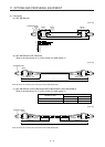
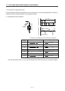
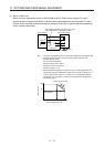
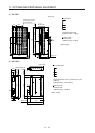
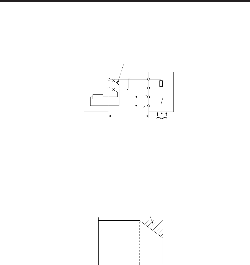
(1) MR-JE-100B or less
When you use a regenerative option for MR-JE-40B to MR-JE-100B, remove wirings of P+ and C,
remove the built-in regenerative resistor, and then connect the regenerative option between P+ and C.
G3 and G4 are terminals for the thermal sensor. Between G3 and G4 is opened when the regenerative
option overheats abnormally.
Always remove the wiring (across P+ to C) of th
e
servo amplifier built-in regenerative resistor.
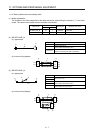
P+
C
G4
G3
C
P
Regenerative option
5 m or less
Servo amplifier
(Note 2)
(Note 1)
Cooling fan
(Note 3)
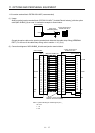
Note 1. The built-in regenerative resistor is not provided for MR-JE-10B and MR-JE-20B.
2. Configure a sequence which will switch off the magnetic contactor when
abnormal heating occurs.
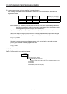
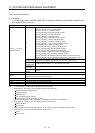
G3-G4 contact specifications
Maximum voltage: 120 V AC/DC
Maximum current: 0.5 A/4.8 V DC
Maximum capacity: 2.4 VA
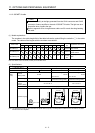
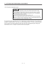
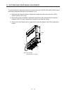
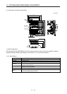
3. When the ambient temperature is higher than 55 °C and the regenerative load
ratio is higher than 60% in MR-RB32, forcibly cool the air with a cooling fan (1.0
m
3
/min or more, 92 mm × 92 mm). A cooling fan is not required if the ambient
temperature is 35 °C or lower. (A cooling fan is required for the shaded area in
the following graph.)
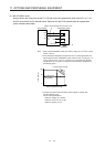
100
60
0
0
Ambient temperature [°C]
35 55
A cooling fan is
not required.
A cooling fan is required.
Load ratio [%]