


APPENDIX
App. - 11
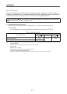
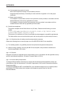
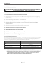
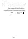
App. 4.4.2 I/O device
The following shows typical I/O devices of MR-JE-_A. For the other devices, refer to each servo amplifier
instruction manual.
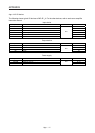
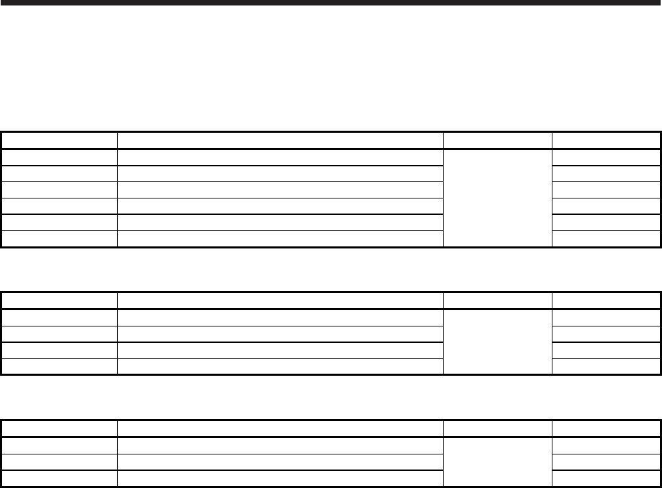
Input device
Symbol Device Connector Pin No.
SON Servo-on
CN1
15
RES Reset 19
CR Clear 41
EM2 Forced stop 2 42
LSP Forward rotation stroke end 43
LSN Reverse rotation stroke end 44
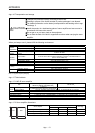
Output device
Symbol Device Connector Pin No.
ZSP Zero speed detection
CN1
23
INP In-position 24
ALM Malfunction 48
RD Ready 49
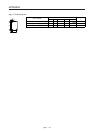
Power supply
Symbol Device Connector Pin No.
DICOM Digital I/F power supply input 20, 21
DOCOM Digital I/F common CN1 46, 47
SD Shield Plate