4 - 46
4. OPERATION
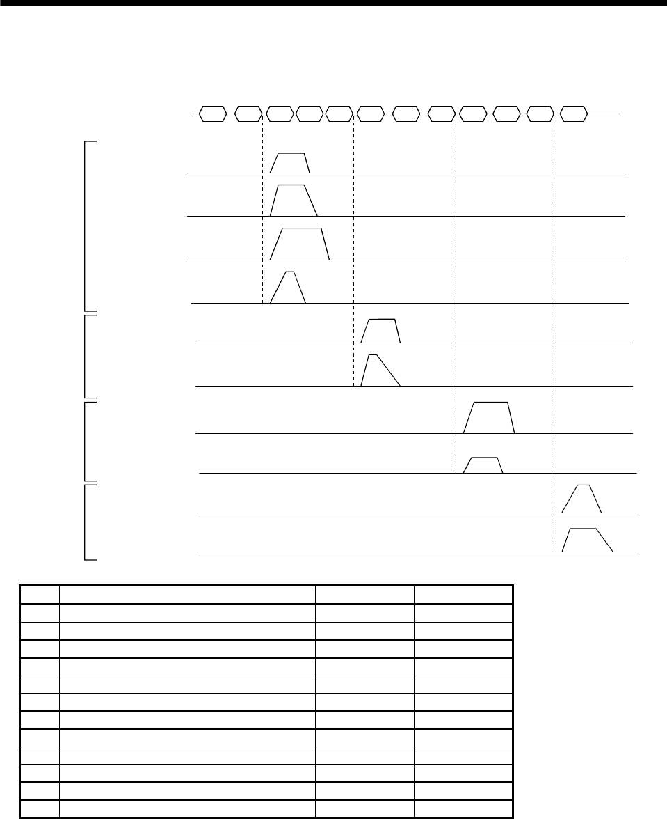
(2) Timing chart
In the following timing chart, operation is performed group-by-group in accordance with the values set
in point table No.1.
Transmission data
Station 0
Servo motor
speed
1)
2) 4) 5)
7)
8)
10)
Station 1
Servo motor
speed
Station 2
Servo motor
speed
Station 3
Servo motor
speed
Station 4
Servo motor
speed
Station 5
Servo motor
speed
Station 6
Servo motor
speed
Station 7
Servo motor
speed
Station 8
Servo motor
speed
Station 9
Servo motor
speed
Group a
Group b
Group c
Group d
3) 6)
9) 11) 12)
No. Transmission data Command Data No.
1) Selection of point table No.1 of group a [9] [2] [6] [0]
2) Forward rotation start (ST1) ON [9] [2] [6] [0]
3) Forward rotation start (ST1) OFF [9] [2] [6] [0]
4) Selection of point table No.1 of group b [9] [2] [6] [0]
5) Forward rotation start (ST1) ON [9] [2] [6] [0]
6) Forward rotation start (ST1) OFF [9] [2] [6] [0]
7) Selection of point table No.1 of group c [9] [2] [6] [0]
8) Forward rotation start (ST1) ON [9] [2] [6] [0]
9) Forward rotation start (ST1) OFF [9] [2] [6] [0]
10) Selection of point table No.1 of group d [9] [2] [6] [0]
11) Forward rotation start (ST1) ON [9] [2] [6] [0]
12) Forward rotation start (ST1) OFF [9] [2] [6] [0]
In addition, parameter values common to the stations of each group can be written and alarm reset
can be made, for example.
(3) Group setting instructions
Only one servo amplifier may send a reply in any group. If two or more servo amplifiers send reply
data at the same time, they may become faulty.


