


5 - 9
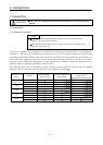
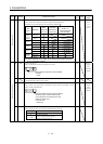
5. PARAMETERS
Class No. Symbol Name and Function
Initial
value
Unit
Setting
range
Basic parameters
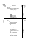
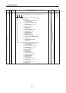
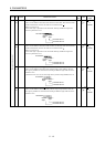
18 *DMD Status display selection
Used to select the status display shown at power-on. (Refer to section 7.2)
Status display on servo amplifier display
at power-on
00: Current position (initial value)
01: Command position
02: Command remaining distance
03: Point table No.
04: Cumulative feedback pulses
05: Servo motor speed
06: Droop pulses
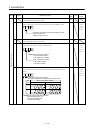
07: Override voltage
08: Analog torque limit voltage
09: Regenerative load ratio
0A: Effective load ratio
0B: Peak load ratio
0C: Instantaneous torque
0D: Within one-revolution position low
0E: Within one-revolution position high
0F: ABS counter
10: Load inertia moment ratio
11: Bus voltage
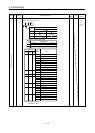
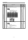
Status display of MR-DP60 at power-on
00: Current position (initial value)
01: Command position
02: Command remaining distance
03: Point table No.
04: Cumulative feedback pulses
05: Servo motor speed
06: Droop pulses
07: Override voltage
08: Analog torque limit voltage
09: Regenerative load ratio
0A: Effective load ratio
0B: Peak load ratio
0C: Instantaneous torque
0D: Within one-revolution position
0E: ABS counter
0F: Load inertia moment ratio
10: Bus voltage
0000 Refer to
Name
and
function
column.