


3 - 11
3. SIGNALS AND WIRING
(2) Input signal
For the input interfaces (symbols in I/O column in the table), refer to section 3.6.2.
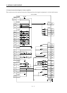
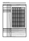
Signal
Signal
symbol
Connector
pin No.
Functions/Applications
I/O
division
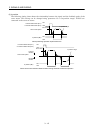
PP CN1A-3 Manual pulse
generator
NP CN1A-2
Used to connect the manual pulse generator (MR-HDP01).
For details, refer to section 14.1.8.
Override VC CN1B-2 10 to 10V is applied to across VC-LG to limit the servo motor speed.
Apply
10[V] for 0[%] override, 0[V] for 100[%], or 10[V] for 200[%].
Analog
input
Analog torque limit TLA CN1B
12
To use this signal, set any of MR Configurator (servo configuration
software) to make the external torque limit selection (TL) available.
When the analog torque limit (TLA) is valid, torque is limited in the full
servo motor output torque range. Apply 0 to
10VDC across TLA-LG.
Connect the positive terminal of the power supply to TLA. Maximum
torque is generated at
10V. (Refer to in section 3.4.4.) Resolution:10bits
Analog
input
(3) Output signal
For the output interfaces (symbols in I/O column in the table), refer to section 3.6.2.
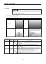
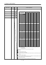
Signal
Signal
symbol
Connector
pin No.
Functions/Applications
I/O
division
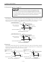
Encoder Z-phase pulse
(open collector)
OP CN1A
14
Outputs the zero-point signal of the encoder. One pulse is output per
servo motor revolution. OP and LG are connected when the zero-point
position is reached. (Negative logic)
The minimum pulse width is about 400
s. For home position return
using this pulse, set the creep speed to 100r/min. or less.
DO-2
Encoder A-phase pulse
(differential line driver)
LA
LAR
CN1A
6
CN1A
16
DO-2
Encoder B-phase pulse
(differential line driver)
LB
LBR
CN1A
7
CN1A
17
Outputs pulses per servo motor revolution set in parameter No. 27 in the
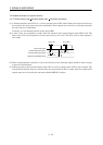
differential line driver system. In CCW rotation of the servo motor, the
encoder B-phase pulse lags the encoder A-phase pulse by a phase angle
of
/2.
The relationships between rotation direction and phase difference of the
A- and B-phase pulses can be changed using parameter No. 58.
DO-2
Encoder Z-phase pulse
(differential line driver)
LZ
LZR
CN1A
5
CN1A
15
The same signal as OP is output in the differential line driver system.
DO-2
Analog monitor 1 MO1 CN3
4
Used to output the data set in parameter No.17 to across MO1-LG in
terms of voltage. Resolution 10 bits
Analog
output
Analog monitor 2 MO2 CN3
14
Used to output the data set in parameter No.17 to across MO2-LG in
terms of voltage. Resolution 10 bits
Analog
output