


3 - 27
3. SIGNALS AND WIRING
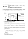
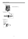
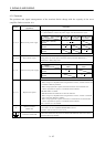
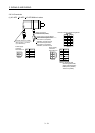
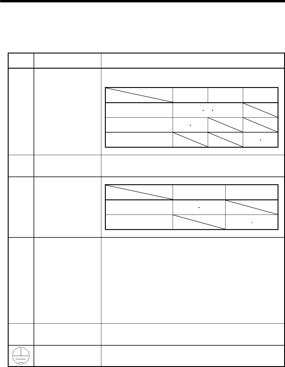
3.7.2 Terminals
The positions and signal arrangements of the terminal blocks change with the capacity of the servo
amplifier. Refer to section 12.1.
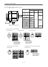
Symbol
Connection Target
(Application)
Description
Supply L
1
, L
2
and L
3
with the following power.
For 1-phase 230VAC, connect the power supply to L
1
/L
2
and leave L
3
open.
Servo amplifier
Power supply
MR-J2S-10CP
to 70CP
MR-J2S-100CP
to 700CP
MR-J2S-10CP1
to 40CP1
3-phase 200 to 230VAC,
50/60Hz
L
1
L
2
L
3
1-phase 230VAC,
50/60Hz
L
1
L
2
1-phase 100 to 120VAC,
50/60Hz
L
1
L
2
L
1
, L
2
, L
3
Main circuit power supply
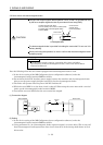
U, V, W Servo motor output
Connect to the servo motor power supply terminals (U, V, W).
During power-on, do not open or close the motor power line. Otherwise, a
malfunction or faulty may occur.
Servo amplifier
Power supply
MR-J2S-10CP to
700CP
MR-J2S-10CP1 to
40CP1
1-phase 200 to 230VAC,
50/60Hz
L
11 L21
1-phase 100 to 120VAC,
50/60Hz
L
11 L21
L
11
, L
21
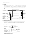
Control circuit power supply
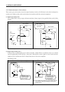
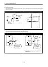
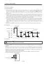
P, C, D Regenerative option
1) MR-J2S-350CP or less
When using servo amplifier built-in regenerative resistor, connect between P-D
terminals. (Wired by default)
When using regenerative option, disconnect between P-D terminals and
connect regenerative option to P terminal and C terminal.
2) MR-J2S-500CP or 700CP
MR-J2S-500CP and 700CP do not have D terminal.
When using servo amplifier built-in regenerative resistor, connect P terminal
and C terminal. (Wired by default)
When using regenerative option, disconnect P terminal and C terminal and
connect regenerative option to P terminal and C terminal.
Refer to section 14.1.1 for details.
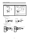
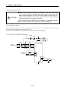
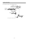
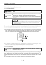
N
Return converter
Brake unit
When using brake unit, connect to P terminal and N terminal.
Do not connect to servo amplifier MR-J2S-200CP or less.
For details, refer to section 14.1.2, 14.1.3.
Protective earth (PE)
Connect this terminal to the protective earth (PE) terminals of the servo motor
and control box for grounding.