


3 - 4
3. SIGNALS AND WIRING
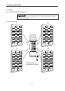
3.3 I/O signals
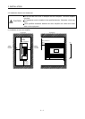
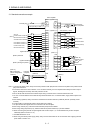
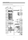
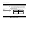
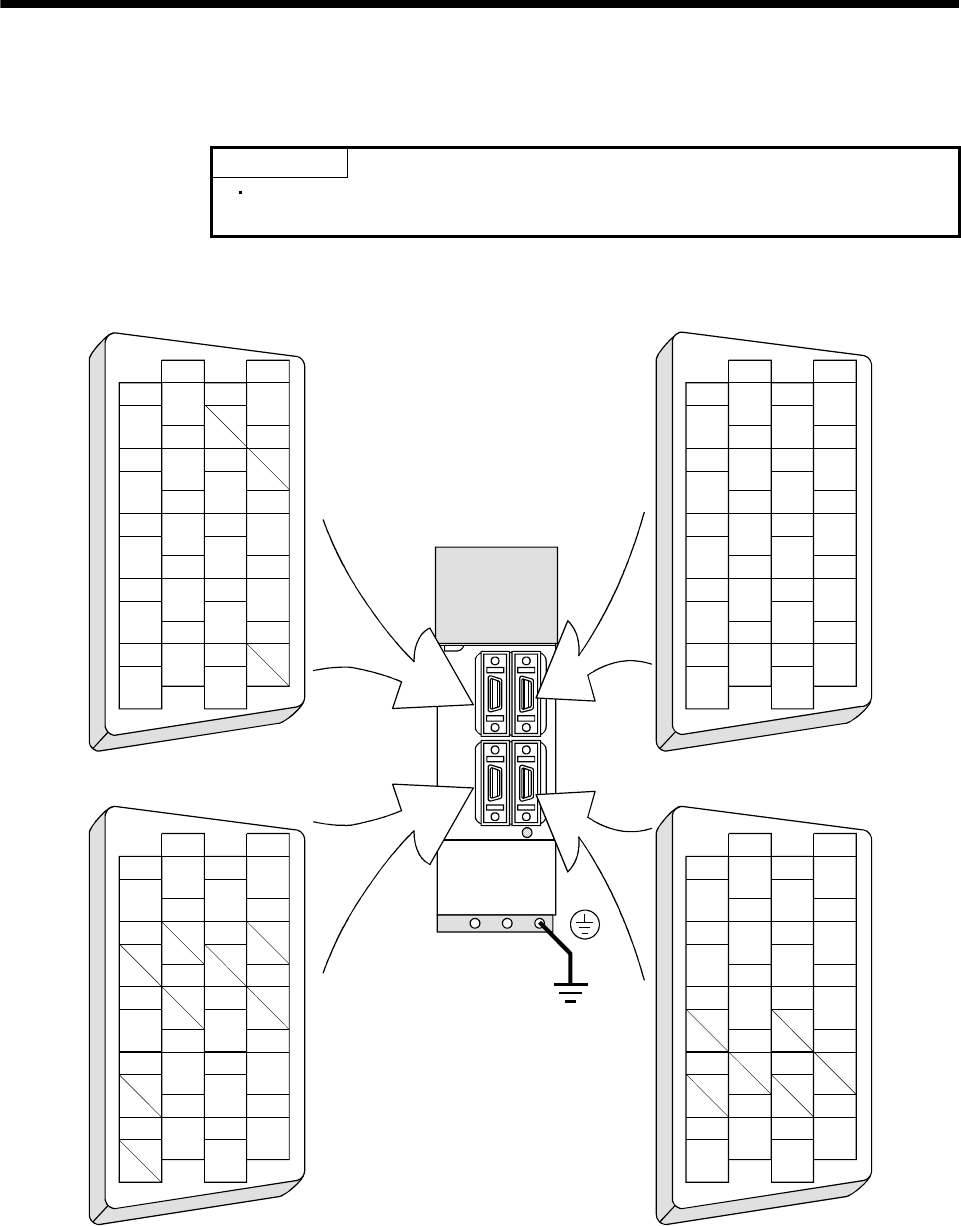
3.3.1 Connectors and signal arrangements
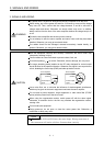
POINT
The connector pin-outs shown above are viewed from the cable connector
wiring section side.
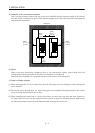
(1) Signal arrangement
1
2
3
5
4
6
7
9
8
10
11
12
13
14
15
16
17
18
19
20
RXD
MO1
TRE
LG
LG
RDP
SDP
TXD
MO2
P5
LG
LG
RDN
SDN
1
2
3
5
4
6
7
9
8
10
11
12
13
14
15
16
17
18
19
20
1
2
3
5
4
6
7
9
8
10
11
12
13
14
15
16
17
18
19
20
1
2
3
5
4
6
7
9
8
10
11
12
13
14
15
16
17
18
19
20
MD
LG
MDR
P5
LG
MRR
P5
LG
P5
BAT
MR
LG
Servo amplifier
CN2 CN3
CN1
A
CN1B
The connector frames are
connected with the PE (earth)
terminal inside the servo amplifier.
LG
NP
P15R
DOG
SG
COM
PP
OPC
ZP
SG
LG
SG
SG
COM
SON
LSN
MD0
ST1
ST2
MEND
DI0
VDD
CPO
LSP
ALM
DI1
TLA
P15R
VC
RD
LA
LB
LZ
LAR
OP
LZR
LBR