


1 - 4
1. FUNCTIONS AND CONFIGURATION
1.1.2 System configuration
This section describes operations using this servo.
You can arrange any configurations from a single-axis to max. 32-axis systems. Further, the connector
pins in the interface section allow you to assign the optimum signals to respective systems. (Refer to
sections 1.1.3 and 3.3.2.) The MR Configurator (servo configuration software) (refer to chapter 6) and
personal computer are required to change or assign devices.
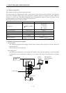
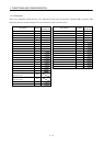
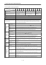
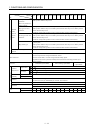
Set the following values to the point table.
Name Setting range Unit
Position data 999999 to 999999
0.001[mm]
0.01[mm]
0.1[mm]
1[mm]
Servo motor speed 0 to max. speed [r/min]
Acceleration time constant 0 to 20000 [ms]
Deceleration time constant 0 to 20000 [ms]
Dwell 0 to 20000 [ms]
Auxiliary function
0 to 3
(Refer to section 4.2)
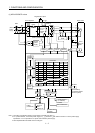
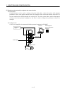
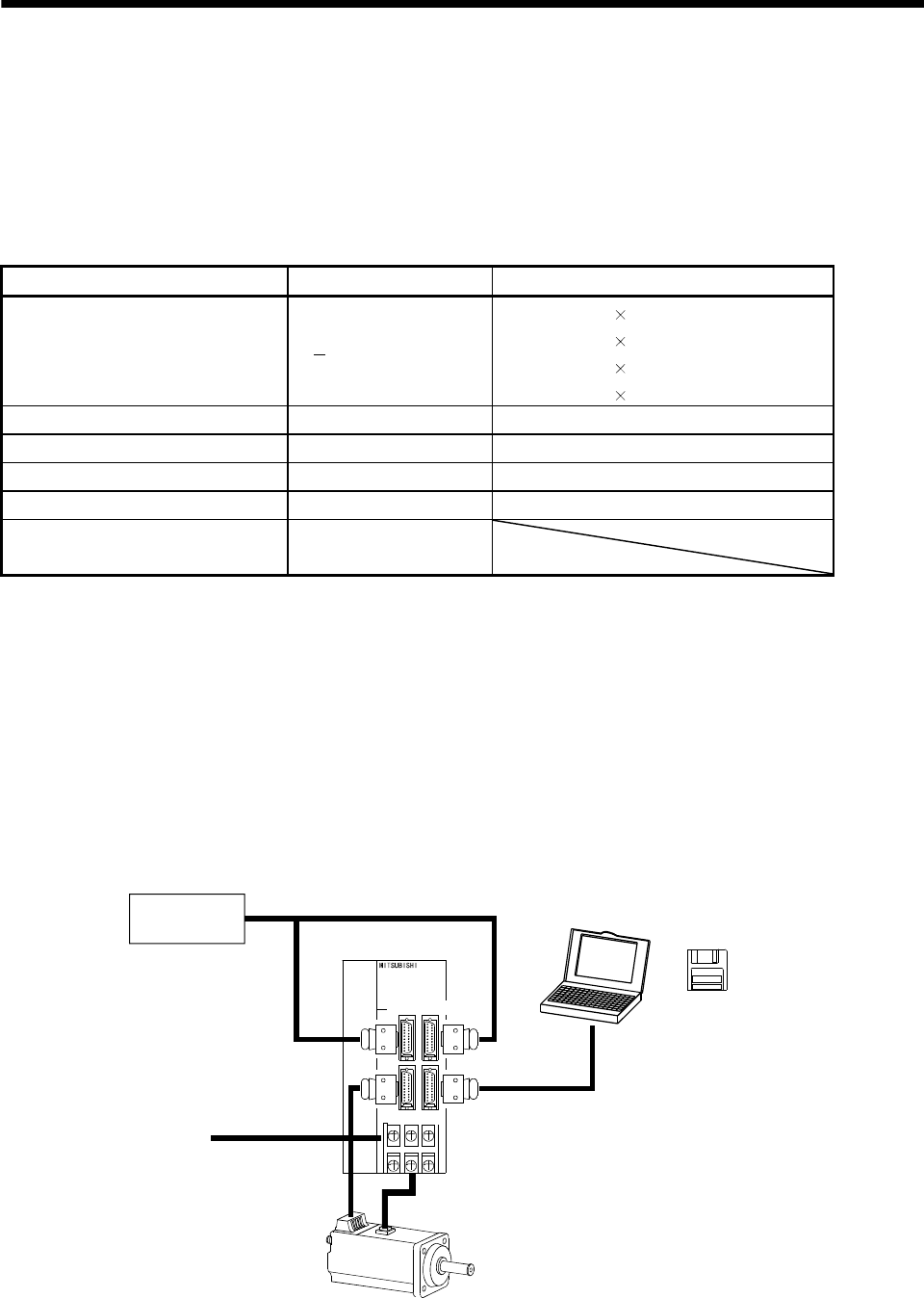
(1) Operation using external input signals
(a) Description
The following configuration example assumes that external input signals are used to control all
signals (devices).
The I/O signals are as factory-set.
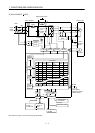
(b) Configuration
The following configuration uses external I/O signals. The personal computer is used with MR
Configurator (servo configuration software) to set, change and monitor the parameters and point
tables.
Servo amplifier
External I/O
signals
Power supply
Servo motor
RS–232C
MR Configurator
(Servo configuration
Software)
Personal
computer
CN1A CN1B
CN2 CN3