


4 - 3
4. OPERATION
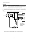
(2) Startup procedure
(a) Power on
1) Switch off the servo-on (SON).
2) When main circuit power/control circuit power is switched on, "PoS" (Current position) appears
on the servo amplifier display.
In the absolute position detection system, first power-on results in the absolute position lost
(AL.25) alarm and the servo system cannot be switched on. This is not a failure and takes place
due to the uncharged capacitor in the encoder.
The alarm can be deactivated by keeping power on for a few minutes in the alarm status and
then switching power off once and on again.
Also in the absolute position detection system, if power is switched on at the servo motor speed
of 500r/min or higher, position mismatch may occur due to external force or the like. Power must
therefore be switched on when the servo motor is at a stop.
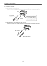
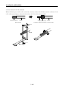
(b) Test operation
Using jog operation in the "test operation mode" of the MR Configurator (servo configuration
software), confirm that the servo motor operates at the slowest speed. (Refer to section 6.7.1, 7.9.2)
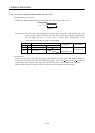
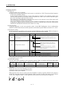
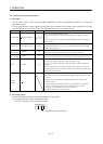
(c) Parameter setting
Set the parameters according to the structure and specifications of the machine. Refer to chapter 5
for the parameter definitions and to sections 6.4 and 7.6 for the setting method.
Parameter Name Setting Description
No.0
Command system, regenerative
option selection
No.1 Feeding function selection
No.2 Function selection 1
20
Absolute value command system.
MR-RB032 regenerative option is used.
10
When forward rotation start (ST1) is
valid, address is incremented in CCW
direction.
Since command resolution is 10 times,
feed length multiplication factor of 10
times is selected.
Absolute position detection system.
1
No.4 Electronic gear numerator (CMX)
32768 From calculation result of formula (4.1)
No.5 Electronic gear denominator (CDV)
1250 From calculation result of formula (4.1)
After setting the above parameters, switch power off once. Then switch power on again to make the
set parameter values valid.
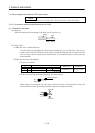
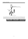
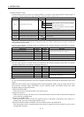
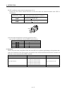
(d) Point table setting
Set the point table according to the operation pattern. Refer to section 4.2 for the point table
definitions and to sections 6.5 and 7.5 for the setting method.
Position data
[
10
STM
m]
Servo motor
speed[r/min]
Acceleration time
constant[ms]
Deceleration time
constant[ms]
Dwell [ms]
Auxiliary
function
20000 2500 200 300 0 0
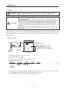
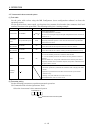
(e) Servo-on
Switch the servo-on in the following procedure.
1) Switch on main circuit/control circuit power.
2) Switch on the servo-on (SON).
When placed in the servo-on status, the servo amplifier is ready to operate and the servo motor is
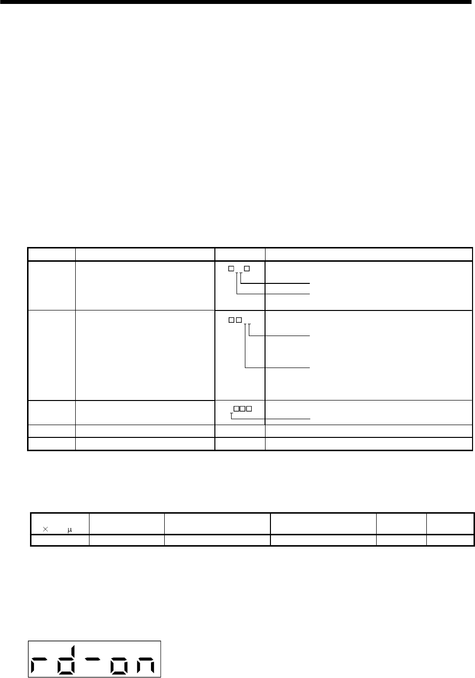
locked. By using the sequence in the diagnostic mode in section 7.3, the ready status can be shown
on the servo amplifier display. In the operation-ready status, the following screen appears.