


5 - 12
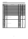
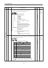
5. PARAMETERS
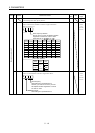
Class No. Symbol Name and Function
Initial
value
Unit
Setting
range
31 MO1 Analog monitor 1 (MO1) offset
Used to set the offset voltage of the analog monitor 1 (MO1) output.
0 mV 999 to
999
32 MO2 Analog monitor 2 (MO2) offset
Used to set the offset voltage of the analog monitor 2 (MO2) output.
0 mV 999 to
999
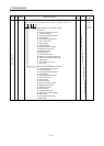
33 MBR Electromagnetic brake sequence output
Used to set the delay time (Tb) between when the electromagnetic brake
interlock (MBR) switches off and when the base circuit is shut off.
(Refer to section 3.9)
100 ms 0 to 1000
34 GD2 Ratio of load inertia moment to servo motor inertia moment
Used to set the ratio of the load inertia moment to the servo motor shaft
inertia moment. (Refer to chapter 8)
When auto tuning is selected, the result of auto tuning is automatically set.
70
0.1
times
0 to 1000
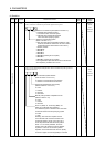
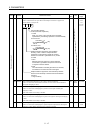
35 PG2 Position control gain 2
Used to set the gain of the position loop. (Refer to chapter 8)
Set this parameter to increase the position response level to load disturbance.
Higher setting increases the response level but is liable to generate vibration
and/or noise.
When auto tuning is selected, the result of auto tuning is automatically set.
35 rad/s 1 to 1000
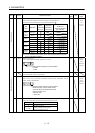
36 VG1 Speed control gain 1
Normally this parameter value need not be changed.
Higher setting increases the response level but is liable to generate vibration
and/or noise. (Refer to chapter 8)
When auto tuning is selected, the result of auto tuning is automatically set.
177 rad/s 20 to
8000
37 VG2 Speed control gain 2
Set this parameter when vibration occurs on machines of low rigidity or large
backlash. Higher setting increases the response level but is liable to generate
vibration and/or noise. (Refer to chapter 8)
When auto tuning is selected, the result of auto tuning is automatically set.
817 rad/s 20 to
20000
38 VIC Speed integral compensation
Used to set the integral time constant of the speed loop. (Refer to chapter 8)
When auto tuning is selected, the result of auto tuning is automatically set.
48 ms 1 to 1000
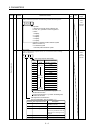
39 VDC Speed differential compensation
Used to set the differential compensation. (Refer to chapter 8)
Made valid when the proportion control (PC) is switched on.
980 0 to 1000
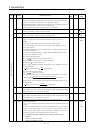
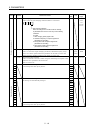
40 0
41
For manufacturer setting
Do not change this value by any means.
0
42 *ZPS Home position return position data
Used to set the current position on completion of home position return.
(Refer to section 4.4)
0
10
STM
m
32768
to
32767
43 DCT Moving distance after proximity dog
Used to set the moving distance after proximity dog in count type home
position return. (Refer to section 4.4.3)
1000
10
STM
m
0 to
65535
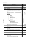
44 ZTM Stopper type home position return stopper time
In stopper type home position return, used to set the time from when the
machine part is pressed against the stopper and the torque limit set in
parameter No.45 is reached to when the home position is set.
(Refer to section 4.4.5)
100 ms 5 to 1000
Expansion parameters 1
45 ZTT Stopper type home position return torque limit
Used to set the torque limit value relative to the max. torque in [%] in stopper
type home position return. (Refer to section 4.4.5)
15 % 1 to 100