


3 - 12
3. SIGNALS AND WIRING
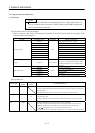
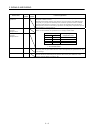
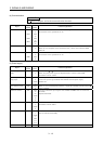
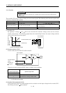
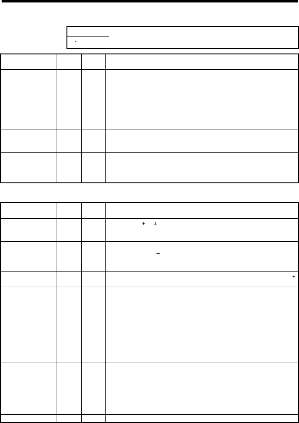
(4) Communication
POINT
Refer to chapter 15 for the communication function.
Signal
Signal
symbol
Connector
pin No.
Functions/Applications
RS-422 I/F SDP
SDN
RDP
RDN
CN3
9
CN3
19
CN3
5
CN3
15
RS-422 and RS-232C functions cannot be used together.
Choose either one in parameter No. 16.
RS-422 termination TRE CN3
10
Termination resistor connection terminal of RS-422 interface.
When the servo amplifier is the termination axis, connect this terminal to RDN
(CN3-15).
RS-232C I/F TXD
RXD
CN3
2
CN3
12
RS-422 and RS-232C functions cannot be used together.
Choose either one in parameter No. 16.
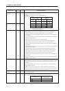
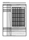
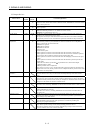
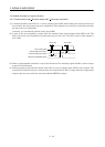
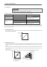
(5) Power supply
Signal
Signal
symbol
Connector
pin No.
Functions/Applications
I/F internal power
supply
VDD CN1B
3
Used to output 24V 10% to across VDD-SG.
When using this power supply for digital interface, connect it with COM.
Permissible current : 80mA
Digital I/F power
supply input
COM CN1A
9
CN1B
13
Used to input 24VDC (200mA or more) for input interface.
Connect the positive (
) terminal of the 24VDC external power supply.
24VDC 10%
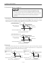
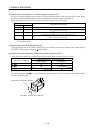
Open collector power
input
OPC CN1A
11
When you use a manual pulse generator , supply this terminal with the positive ( )
power of 24VDC.
Digital I/F common SG CN1A
10
20
CN1B
10
20
Common terminal for input signals such as SON and EMG. Pins are connected
internally.
Separated from LG.
15VDC power supply P15R CN1A
4
CN1B
11
Outputs 15VDC to across P15R-LG. Available as power for VC and VLA.
Permissible current: 30mA
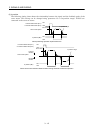
Control common LG CN1A
1
CN1B
1
CN3
1, 11
3, 13
Common terminal for TLA, VC, OP, MO1, MO2 and P15R.
Pins are connected internally.
Shield SD Plate Connect the external conductor of the shield cable.