


1 - 2
1. FUNCTIONS AND CONFIGURATION
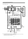
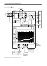
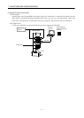
(1) MR-J2S-350CP or less
1000
0
80
100
100
0
(
Note 2
)
Power
suppl
y
NFB
MC
Servo amplifier
Regenerative option
(Note 1)
PDC
Diode
stack
Relay
L
1
L2
L3
CHARGE
lamp
Regenerative
transistor
Dynamic
brake
Current
detector
Servo motor
M
U
V
W
U
V
W
B2
B1
Encoder
Electro-
magnetic
brake
CN2
L
11
L21
(Note 3) Cooling fan
Base
amplifier
Voltage
detection
Overcurrent
protection
Control
power
supply
Current
detection
Point table
I/F
A/D
CN1A CN1B
RS-232C
RS-422
D/A
CN3
CON1
MR-BAT
Optional battery
(for absolute position
detection system)
D I/O control
Servo on
Start
Failure, etc.
Analog
(2 channels)
To other servo
amplifier
RS-422/RS-232C
Controller
Analog monitor
(2 channels)
1
31
8
7
6
5
4
3
2
1000
2000
4000
500
1000
2000
1000
1000
2000
2000
1000
1000
2000
2000
2000
2000
1000 80
100
70
60
80
80
80
100
80
80
100
70
60
80
80
100
80
1000
500
0
0
0
0
0
0
0
0
0
0
0
0
0
1
1
No.
Model adaptive control
Current
control
Position
control
Speed
control
Position
command
creation
Auxiliary
Dwell
Position
data
Speed
Acceleration
time
constant
Deceleration
time
constant
1000
Note 1. The built-in regenerative resistor is not provided for the MR-J2S-10CP (1).
2. For 1-phase 230VAC, connect the power supply to L
1
, L
2
and leave L
3
open. Refer to section 1.2 for the power supply
specification. L
3
is not provided for a 1-phase 100 to120VAC power supply.
3. Servo amplifiers MR-J2S-200CP have a cooling fan.