


3 - 3
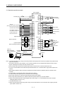
3. SIGNALS AND WIRING
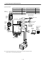
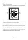
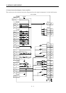
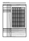
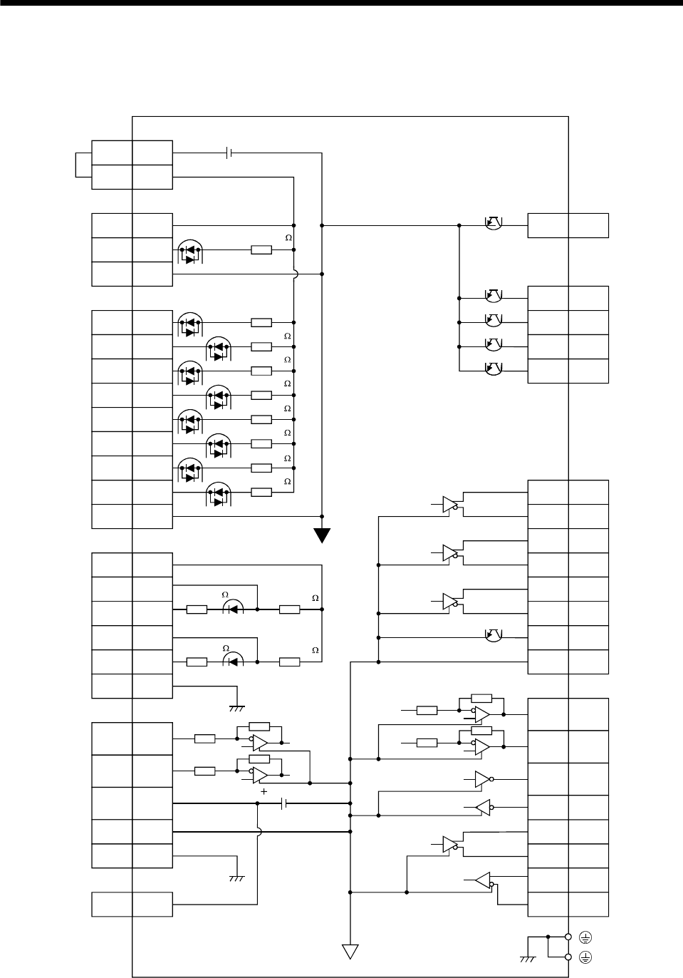
3.2 Internal connection diagram of servo amplifier
This section gives the internal connection diagram where the signal assignment is in the initial status.
Servo amplifier
VDD
COM
COM
DOG
SG
DI0
MD0
ST1
ST2
DI1
SON
LSP
LSN
SG
CN1B
3
13
9
8
5
7
8
9
14
15
16
17
10, 20
10, 20
OPC
PG
PP
NG
NP
SD
11
13
3
12
2
Casing
CN1A
CN1B
VC
TLA
P15R
LG
SD
2
12
11
1
Casing
CN1A
P15R
4
24VDC
Approx. 4.7k
Approx. 4.7k
Approx. 4.7k
Approx. 4.7k
Approx. 4.7k
Approx. 4.7k
Approx. 4.7k
Approx. 4.7k
Approx. 100
Approx. 1.2k
Approx. 1.2k
15VDC
ZP
CPO
MEND
ALM
RD
18
4
6
18
19
CN1A
CN1B
CN1A
16
7
17
5
14
1
15
6
LG
MO1
4
CN3
MO2
LA
LAR
LB
LZ
LZR
OP
LBR
14
2
12
9
19
5
15
RXD
TXD
SDP
SDN
RDP
RDN
PE
CN1A
CN1B
Approx. 100