


14 - 30
14. OPTIONS AND AUXILIARY EQUIPMENT
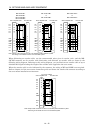
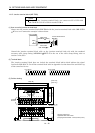
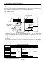
14.1.7 External digital display (MR-DP60)
The data equivalent to the servo amplifier status display can be displayed on the MR-DP60. When using
the MR-DP60, set "
1 4" in parameter No. 16. The items that appear at the time of power-on can be
selected in parameter No.18.
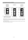
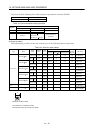
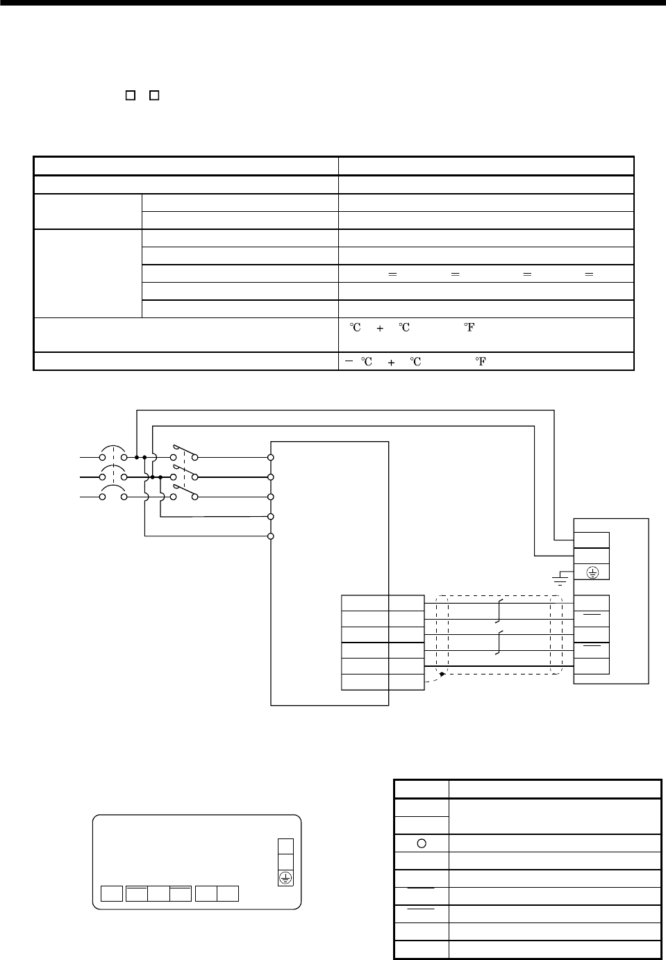
(1) Specifications
Item Specifications
Display Red seven-segment LED, signed, six digits
Permissible voltage fluctuation Single-phase, 85 to 253VAC, 50/60Hz Power supply
Current consumption Within 200mA
Interface Conforms to RS-422
Baud rate 4800bps, asynchronous
Bit length Start bit 1, date bit 8, parity bit 1, stop bit 1
Protocol MELSERVO protocol
Communication
Communication commands Commands dedicated to MELSERVO
Operating temperature / humidity range 0 to 60 (32 to 140 ),
90%RH or less, non-condensing
Storage temperature range 5 to 70 (23 to 158 )
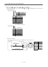
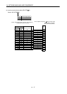
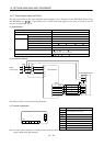
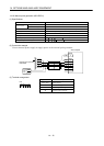
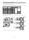
(2) Connection example
(Note)
Power supply
Servo amplifier
NFB
RDN
SDP
SDN
LG
SD
RDP5
15
9
19
1
CN3
Plate
External digital display
MR-DP60
L
1
L
2
TXD
TXD
RXD
LG
RXD
L1
L
2
L
3
L
11
L
21
MC
Note. Refer to section 1.2 for the power supply specification.
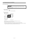
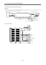
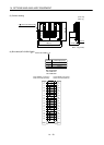
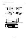
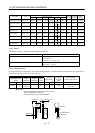
(3) Terminal arrangement
Signal Description
L1
L2
100 to 230VAC power input
Ground
RXD Receive signal input
RXD Inverse receive signal input
TXD Inverse transmission signal output
TXD Transmission signal output
P5 5VDC output (Note)
TB2
L
1
L2
TXD TXD RXDRXD P5 LG
TB1
LG Control common
Note. The 5VDC output is designed for the internal control circuit and used to make a voltage check, etc. Do not use this terminal to
supply a voltage to the other equipment.