


14 - 43
14. OPTIONS AND AUXILIARY EQUIPMENT
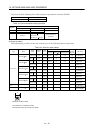
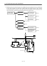
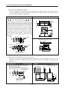
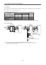
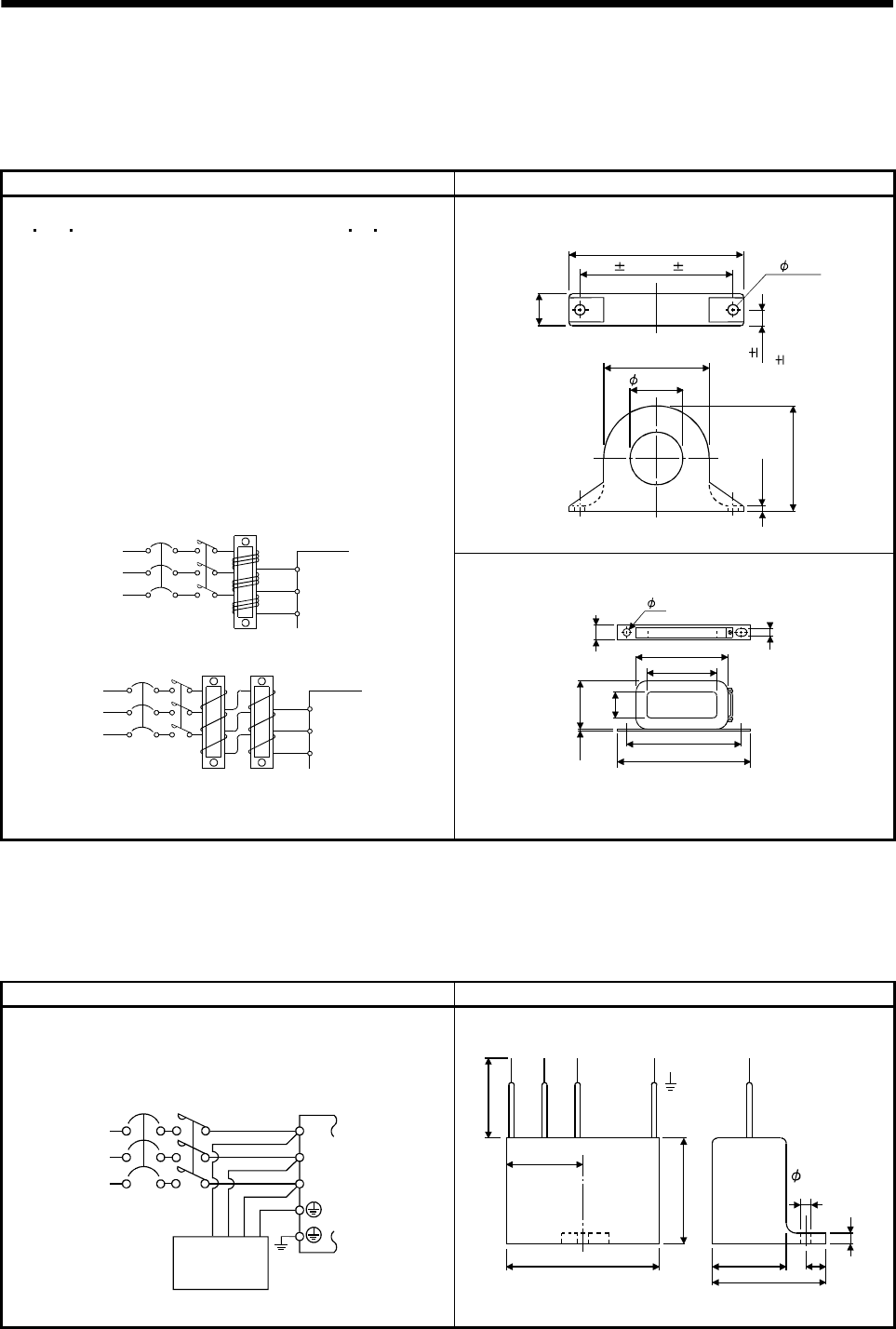
(d) Line noise filter (FR-BLF, FR-BSF01)
This filter is effective in suppressing noises radiated from the power supply side and output side of
the servo amplifier and also in suppressing high-frequency leakage current (zero-phase current)
especially within 0.5MHz to 5MHz band.
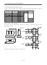
Connection diagram Outline drawing [Unit: mm] ([Unit: in.])
4
.
5
(
0
.
1
8
)
Approx.110(4.33)
A
p
p
r
o
x
2
2
.
5
(
0
.
8
9
)
A
p
p
r
o
x
.
6
5
(
2
.
5
6
)
Approx.65 (2.56)
2- 5(0.20)
33(1.30)
1
1
.
2
5
0
.
5
FR-BSF01(for MR-J2S-200CP or less)
95 0.5(3.74 0.02)
(
0
.
4
5
0
.
0
2
)
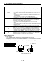
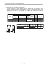
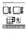
Use the line noise filters for wires of the main power supply
(L
1 L2 L3) and of the motor power supply (U V W). Pass
each of the 3-phase wires through the line noise filter an equal
number of times in the same direction. For the main power supply,
the effect of the filter rises as the number of passes increases, but
generally four passes would be appropriate. For the motor power
supply, passes must be four times or less. Do not pass the
grounding (earth) wire through the filter, or the effect of the filter
will drop. Wind the wires by passing through the filter to satisfy the
required number of passes as shown in Example 1. If the wires
are too thick to wind, use two or more filters to have the required
number of passes as shown in Example 2. Place the line noise
filters as close to the servo amplifier as possible for their best
performance.
Example 2
Two filters are used
(Total number of turns: 4)
Power
supply
Servo amplifier
Line noise
filter
NFB
L
3
L
1
L
2
Example 1
(Number of turns: 4)
Power
supply
NFB
L
1
L
2
L3
Servo amplifier
Line noise
filter
MC
MC
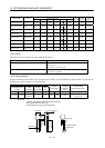
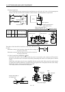
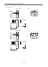
FR-BLF (MR-J2S-350CP or more)
160(6.30)
180(7.09)
130(5.12)
85(3.35)
8
0
(
3
.
1
5
)
2
.
3
(
0
.
0
9
)
3
5
(
1
.
3
8
)
3
1
.
5
(
1
.
2
4
)
7(0.28)
7
(
0
.
2
8
)
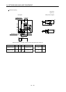
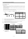
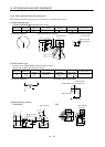
(e) Radio noise filter (FR-BIF)...for the input side only
This filter is effective in suppressing noises radiated from the power supply side of the servo
amplifier especially in 10MHz and lower radio frequency bands. The FR-BIF is designed for the
input only.
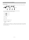
Connection diagram Outline drawing (Unit: mm) ([Unit: in.])
Make the connection cables as short as possible.
Grounding is always required.
When using the FR-BIF with a single-phase wire,
always insulate the wires that are not used for wiring.
Servo amplifier
NFB
L
3
L
2
L1
MC
Power
supply
Radio noise
filter FR-BIF
Leakage current: 4mA
29 (1.14)
58 (2.28)
4
2
(
1
.
6
5
)
4
(
0
.
1
6
)
Red BlueWhite Green
44 (1.73)
29 (1.14)
7 (0.28)
hole
A
b
o
u
t
3
0
0
(
1
1
.
8
1
)
5 (0.20)