3 - 30
3. SIGNALS AND WIRING
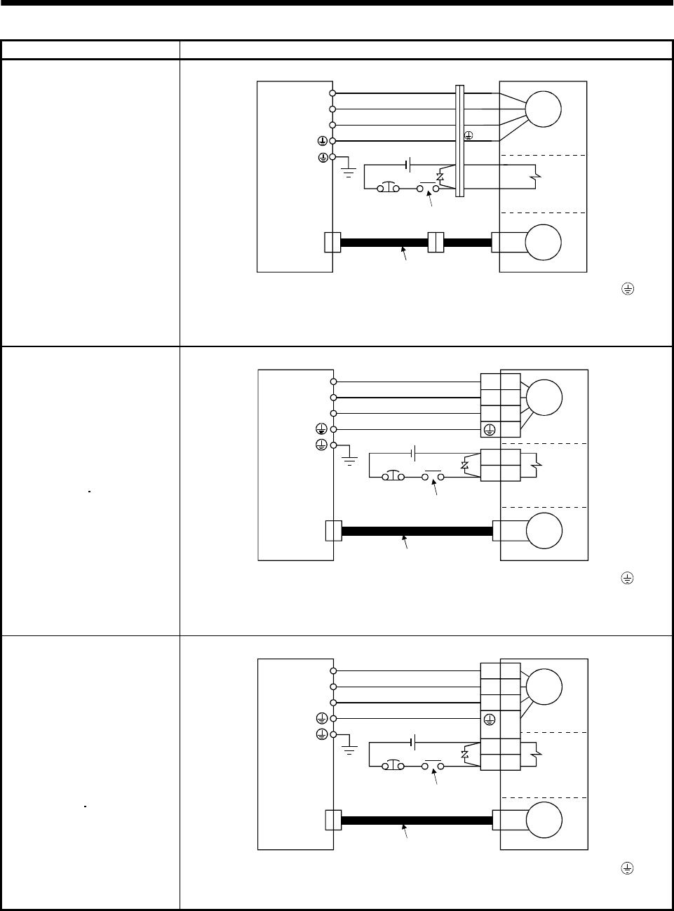
Servo motor Connection diagram
HC-KFS053 (B) to 73 (B)
HC-MFS053 (B) to 73 (B)
HC-UFS13 (B) to 73 (B)
Servo amplifier
(Note 1)
Servo motor
Electromagnetic
brake
24VDC
EMG
(Note 2)
To be shut off when servo-on (SON)
switches off or by Trouble (ALM)
Encoder cable
CN2
Motor
Encoder
U
V
W
B1
B2
U (Red)
V (White)
W (Black)
(Green)
Note 1. To prevent an electric shock, always connect the protective earth (PE) terminal ( ) of the
servo amplifier to the protective earth (PE) of the control box.
2. This circuit applies to the servo motor with electromagnetic brake.
HC-SFS121 (B) to 301 (B)
HC-SFS202 (B) to 702 (B)
HC-SFS203 (B)
353 (B)
HC-UFS202 (B) to 502 (B)
HC-RFS353 (B) to 503 (B)
Electromagnetic
brake
(Note 2)
To be shut off when servo-on (SON)
switches off or by Trouble (ALM)
24VDC
EMG
CN2
U
V
W
U
V
W
B1
B2
Servo amplifier
(Note 1)
Encoder
Encoder cable
Motor
Servo motor
Note 1. To prevent an electric shock, always connect the protective earth (PE) terminal ( ) of the
servo amplifier to the protective earth (PE) of the control box.
2. This circuit applies to the servo motor with electromagnetic brake.
HC-SFS81(B)
HC-SFS52 (B) to 152 (B)
HC-SFS53 (B) to 153 (B)
HC-RFS103 (B) to 203 (B)
HC-UFS72 (B)
152 (B)
Electromagnetic
brake
(Note 2)
To be shut off when servo-on (SON)
switches off or by Trouble (ALM)
24VDC
EMG
CN2
U
V
W
U
V
W
B1
B2
Servo amplifier
(Note 1)
Encoder
Encoder cable
Motor
Servo motor
Note 1. To prevent an electric shock, always connect the protective earth (PE) terminal ( ) of the
servo amplifier to the protective earth (PE) of the control box.
2. This circuit applies to the servo motor with electromagnetic brake.


