


14 - 11
14. OPTIONS AND AUXILIARY EQUIPMENT
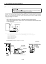
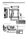
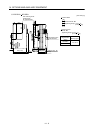
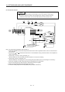
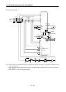
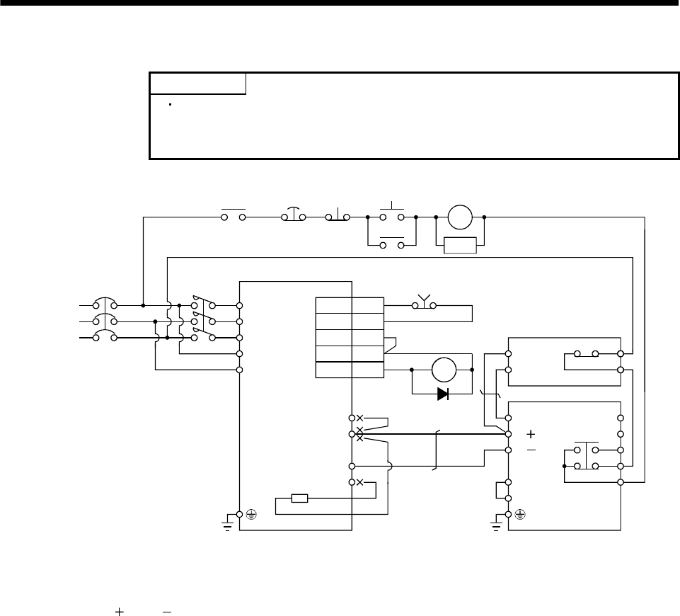
(3) Connection example
POINT
Connecting PR terminal of the brake unit to P terminal of the servo
amplifier results in brake unit malfunction. Always connect the PR
terminal of the brake unit to the PR terminal of the resistor unit.
NFB
ALM
RA1
MC
SK
MC
ON
OFFEMG
(Note 1)
Power
supply
N/
P/
BUE
SD
PR
B
C
A
SD
MSG
(Note 3)
(Note 5)
D
P
N
C
FR-BU2
FR-BR
Servo amplifier
P
PR
TH2
TH1
(Note 4)
MC
(Note 6)
(Note 2)
(Note 7)
L
1
L2
L
3
L11
L
21
(Note 8)
RA1
RA1
3
13
SG
VDD
COM
ALM
10
18
CN1B
EMG
(Note 9)
Note 1. For power supply specifications, refer to section 1.2.
2. For the servo amplifier of 5k and 7kW, always disconnect the lead of built-in regenerative resistor, which is connected to the P
and C terminals.
3. Connect the P/
and N/ terminals of the brake unit to a correct destination. Wrong connection results in servo amplifier and
brake unit malfunction.
4. Contact rating: 1b contact, 110VAC_5A/220VAC_3A
Normal condition: TH1-TH2 is conducting. Abnormal condition: TH1-TH2 is not conducting.
5. Contact rating: 230VAC_0.3A/30VDC_0.3A
Normal condition: B-C is conducting/A-C is not conducting. Abnormal condition: B-C is not conducting/A-C is conducting.
6. For the servo amplifier of 3.5kW, always disconnect the wiring between P and D terminals.
7. Do not connect more than one cable to each P to N terminals of the servo amplifier.
8. Always connect between BUE and SD terminals (Factory-wired).
9. In the device setting, assign the forced stop (EMG) to any pin (Refer to section 6.6).