


Model
3490A
Section
VII
7.T.
INTBODUCTION.
7-2-
This
section
contains
information necessary
for
repairing
the Model
3490A.
Schematic
diagrams, trouble-
shooting
trees,
and
other
troubleshooting and
repair
information
are
included.
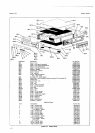
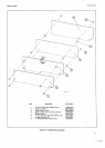
Figure
7-1 7 shows the
location
of
assemblies
within
the 34904. Additional
trouble-
shooting
notes are
located
on schematics.
7.3. PBELIMINARY
TROUBLESHOOTING.
74.
lf the Model
3490A operates
incorrectly
and the
trouble cannot be
corrected by
the
Adjustment Proce-
dures,
the following
troubleshooting
information
should
be used. Check
for loose wires or other obvious sources
of trouble,
such
as
burned
or
loose components.
Make
sure
printed circuit
boards are seated firmly in
connec-
tors. Also
make
sure
those microcircuit
packages
that
mount in sockets
are
filmly seated.
7-5. TRO
UBLESHOOTING TREES.
7-6.
Troubleshooting
information
for
various circuits
or
operations
of
the 3490A is
contained
in several
trouble-
shooting
trees
and associated
information.
The
General
Troubleshooting
Tree,
Figure
7-4,
may be
used to isolate
the problem
to
a
particular
area of the instrument.
The
following
list
indicates
the
circuits
to
which each
tree
applies:
Troubleshooting
Tree
Title
Figure
No.
Standard 3490A
Circuits
SECTION
VII
TBOUBTESHOOTING
AND
CIRCUIT
DIAGRAMS
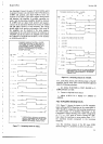
7-7.
ACCESS
F0R
SERVtCtNG.
7-8.
Access to
most areas of the instrument
may be
gained
by
removing the top
cover and
the top guard
cover; It
should not
be necessary to
remoye the
bottom
covers
unless components
on the Main
Circuit Assembly,
Al
,
must be
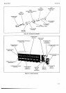
replaced. Remove
the top trim
strip to gain
access
to
the Display
Assembly. The three
vertical
screws
which
secure
the Display
Assembly
heat
sink
to
the
guard
shield
must be removed
in order to
remove
the
Dsplay
Assembly.
The
High Impedance,
AC
Converter
and the
Ohms Converter
printed
circuit boards
and
components
must
be kept clean
and
free
from
fingerprints
or other contamination,
or
performance
may be
degraded.
Handle
these
assemblies
by the
board
extractors.
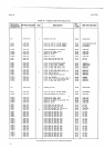
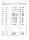
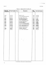
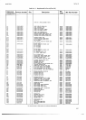
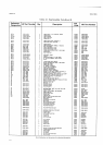
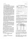
7.9. POWER
SUPPLY CHECKS.
7-10.
Check
the
power
supply voltages
at the points
listed
in Table
7-1 using
an oscilloscope
and a dc
digital
voltmeter
with 4digit
resolution.
Voltage
and ripple
specifications
are as shown. All ripple
measurements
are
to be made
with the
sample rate in the HOLD position.
Voltages
are listed following
the supply
used
as its
reference.
Therefore,
power
supply voltages
should
be
checked
in this order.
The first supply
checked
wtrich
fails
to meet
the voltage
specified is the faulty
supply.
All
supplies referenced
to
the faulty supply
will
also
,
indicate
readings
out
of
specification.
With
the faulty
supply
identified
proceed
to troubleshoot
as follows:
a. Pull
opticns
and install required
jumper
boards. If
problem
disappears,
determine
which option
is
at fault
and
proceed
to its troubleshooting
section.
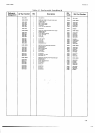
Table 7-1.
Power
Supply
Voltages and Gurrent
Limit
Values.
General
DC
Analog
AC Converter
Ohms
Converter
Display
Logic
Test
hgic
Clock
Option
021
Data
Output
Option
022
Remote
Option 030
cPrB r/o
Option
040
or 045
Sample/Hold
General
Sample/Hold
Logic
Option
080
Ratio
14
n<
7-6
7.7
7-8
7-9
7-ro
7
-lr
7-12
t-13
1-14
7-r5
1-16
Base
Supply
A1A,I
Test
Point
Volrage
Ripple
Current
Limit
{Applox. Voltag€sl
+
17 V
+
5V
+30V
-
17V
-
5V
-
30v
16.99 to
+
17.0'l
V
4.995 to
+
5.075
V
30.10 to+3O.9OV
'16.9
to- 17.1
V
5.00 to
-
5.85 V
30.10
ro-30.90
V
< 50
mV
p-p
(
60
mV
p-p
<
25 mV
p-p
<50mVpf
< 60
mV
p-p
< 25 mV
p-p
Al Rl04
=
.434 V
A1R'l
=
.448 V
Al
R11
'l
=
1.34 v
A1R118
=
.54 V
41R125
=
1.30 V
Raw S0pply
Test
Poinl
Supply
Voltage
Ripple
{Approx.
Voltag€)
TPD
TPA
TPC
24V
24V
38V
38V
9V
24to+28V
24to-
28V
38to+44V
38to- 44V
9to+11V
I vp-p
t.2
v
pf
.5VFp
.5 v
p-p
1.5 V
p-p
1-l