


Model3490A
4:220.
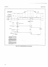
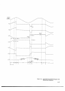
Waveforms
shown
in
Figure
4-31
illustrate
the
measurement
sequence
for
a
single
measurement
on a
sine
wave,
and
the
accompanying
notations
indicate
the
events
occurring
during
the
measurement
sequence'
In
Sample/Hold
measurements,
the
circuits
must
be
in
the
Traci
Mode
from
the
completion
of
one measurement
until
the
receipt
of
the
next
Sample/Hold
Trigger
command.
For
this
reason'
the
DC
Input Amplifier
is
connected
to
the
input
terminals
during
this entire
period,
and
the
normal
auto-zero
cycle
of this amplifier
iatrnot
be
used.
Consequently,
there
is
a
slight offset
voltage
present
in
its output.
This offset
is-removed
from
the Sample/Hold
measurement
voltage
as follows:
a.
The
voltage
at
point 6
(refer
to the diagram
and
waveforms
in
Figure
4-31)
during
the
run-up
period,
3T4,
is
the algebraic
sum
of
the voltages at
points 4 and
S. nre
voltage
at
point 4
is the
sum of
the input
signal
Section
IV
held by
the
Sample/Hold
circuits
and
the
offset
of
the
Input
Amplifier. The
voltage
at
point
5
during
the
same
period
is the inverse of
the
offset voltage.
Ideally,
then,
the
voltage at
point
6
is equal
to
the input
signal
held
by
the
Sample/Hold
circuits
(V4 +
V5
=
input
signal).
b. During
run-down, when
the reference
voltage
is
held
by the Sample/Hold
circuits,
the
same condition
exists.
The voltages
at points 4
and
5 add,
removing
the
Input Amplifier's offset
from the voltage at
point
6.
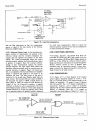
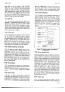
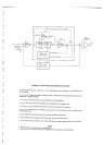
&221. Sample/Hold
Analog
Circuits.
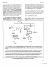
4-222. Circuit
A.
Figure 424 contuns
a
simplified
diagram of
Sample/Hold Circuit
A
and a discussion
of
its
operation.
AMPLIFIE R
A
O
83"
sz
INTEGRATOR
+t7vrt7V
cAPAclroR
@
n'z
OUTPUT
zOK
OF
DC+
INPUT
AMPLIFIER
R20
7t
K
R2l
7tK
NOTEr Sl,S2,A53
ARE
FET
SWITCIES,
AND ARE
STIOWN
IN THE TRACK
MODE STATE
T.
l-
'.,r,*f
v-tNTERNAL
-...
| _,^
CAPACTTANCE
\,,
-t7v
3490-8
-
l39l
a. In
the
Track Mode,
Sl
is
open,
52
and 53
are
closed.
The
circuit from
point
A
to
point
D operates as
an
inverting
unity€ain
amplifier. This
circuit consists
of a
non-inverting amplifier
with
a
gain
of 4 between
points
B and
C,
followed
by an
integrating
amplifier
between
points
C and
D. Very
small
blas
currents
are
required
by
the
FET
source-followers
in the input stage
of the
integrator.
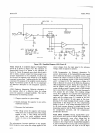
b.
For each
nar
level
of
output
voltage
at
point
D, current
flows
through 52
to readjust the \roltage across
the integrator
capacitor
to
the
appropriae
level.
When
a
Hold A
command is
received,
52
opens and
no more current is supplied
to chang€
the
\toltage
across
the
capacitor,
ln this Hold Mode,
the voltage
at
point
D
remains constant while
a
measurement is
complEted.
c. When
the
Hold
comnrand
occurs, the
gate
voltage on
the FET
switch
52
goes
rcgatiw,
causing
a
current to
flow through the
iunction
capacitance
of
this FET.
This
current alters the \roltage
on the integrator
capacitor.
Compensation
for
this
effect is
provided
by 53,
which
alters
the voltage on
its
associated
capacitor at
the
other
input
to
the amplifier in a similar
fashion.
d. Sl is
closed
during
the Hold Mode.
This
limits the amount of voltage
change
at
point
C, and
prevents
currents
going
from
C
to E through
any
stray capacitance
or through
the internal
capacitance
of
FET switch
52
during the
Hold Mode.
-LCIO
T'oo
I
v
56
Figure
4-24. Simplified
Diagram and Operation of S/H Circuit A.
+23