


Section
VII
7-25.
Replacement
of OCR30l.
7-26.
If
it is
necessary
to
replace
the
reference
transis_
tor-diode
package
AleCR3Ol,
it
is
also
necessary
to
replace
resistors
A1R306,309,
310,
313,
314
and
:t5,
which
are
matched
to
eCR3Ol.
Matched
resistors
are
supplied
with the
replacement
reference,
eCR30l.
7-21.
A-to-D
C0NVERSt0N
CtBCUtT
CHECKS.
7-28.
Ttre
Analogto-Dgital
(A_to_D)
Conversion
circuits
consist
of the
Integrator,
the
x20
Amplifier,
and
the
Zero
Detect
circuits.
Some problern,
in
th"r,
circuits
Tay
be
detected
by
applying
a full_range
input
voltage.
For
example,
the
Integrator
output
*"öfo..
at
AlTpl
may
be checked
with
a
_
lOV
input
on
the
l0Vdc
range.
The
center
portion
of
the
waveform
(10
ms
between
_run-up
and
run_down)
should
be
flat. if
*ri,
portion
decays,
this
may_indicate
leakage
in
the
Integra_
tor
capacitor,
C2O3.If
the
waveform
continues
to
rise,
the
input
switches
e20,1
and
e205
may
not
be
completely
cut
off
during
this
period.
7-29.
..Some
types
of problems,
such
äs
amplifier
offset
or
failure,
may
be
f9un9
UV
setting
the
Sampte
Rate
control
to
HOLD
and
making
dc
voliage
rn.urur"rn.nt,
within
the
circuits.
For
inslance,
boih
inputs
to
an
operational
amplifier
should
be
equal
and
near
zero.
To
check
the
balance
of
a
dual
FST,
such
u,
qZOO
fo.
example,
first
remove
the
microciriuit
ampiifrer
(U201
in
this.case)
from
its
socket.
Connect
Uotf,'pfif
gates
to
ground,
and
measure
the
source
voltages,
which
should
!" :gyd.
These
voltages
may
be
*"urirrä
at
pins
2
and
3
of the
open
U20l
socket.
7-30.
Mth
.the
instrument
sampling
and
with
a
full_
range
input,
the
x20
Amplifier
ouipuishould
not
exceed
|
.2
to
|
.4
V
because
of
the
diodes
i"t*..n
tfr"
amplifier
input
and-output.
Also
with
a
full_range
i"p"t,
tfräZt,r"
detect
reference
voltage
at pin
3
of*U203
should
be
approximately
1 50
mV
during
run_up
una
,u"_Oo*n.,"
No^nJinearity
of
negative
readiigs
rnuy
U,
"uured
by
a
defective
amptifier,
ü201.
7.3I.
INTEGRATOR
TROUBLESHOOTING.
7-32.
the
integrator
may
cause
noise
on
full
scale
readings
in
the
dc
mode.
If
this
occurs,
check
AlR207,
Q206,
Q207,
tJ2Ot
and
u202.If
theie
i,
noirc
at low
input
ievels
(ie.,
100
mV
input
on
l0
V dc
range),
check
AIC2O7.
AlQ209
will
be
very
noisy
if pinch_äff
voltage
is
not
correct.
To
check
for
ä
noisy
eäOg,
increuse
ttre
-
!7y
supply
and
observe
noise.
The
increase
in
the
+
17
V
supply
increases
the
bias
on
aZOS,li
the
noise
9Jt:qq.i"
at
a
higher
+
17
y
,upprv
-uoriuge,
e209
snoud
be
replaced.
Readjust
the
+
17
V
supply
per
Paragraph
5-54.
7.33.
AC
CONVEBTER
TROUBLESHOOTING.
NOTE
The
indication
on
all
ranges
with
the
input
shorted
will
not
be
zero
but
should
be'less
than
50
counts.
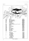
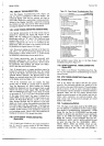
1:7
Model
3490A
Designator
A6-
Spacin g_f
ro
m
corn
ponäit-c"nt",
ro
l,rtnted
Circuit
Board
Minimum
Maximum
cl
c2
c3
c5
R1A
R1B
R44
R4B
R4C
0.1
in
O.1
in
0.1
in
0.1
in
0.4
in
0.1
in
0.4
in
0.1
in
0.1
in
O.2
in
u-2 tn
O.2
in
O.2
in
O.5
in
O.2
in
0.5
in
O.2
in
O.2
in
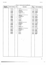
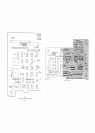
7-34.
Operation
of
the
AC
Converter
circuits
may
be
*::k.9,using
the
Troubleshooting
Tree,
Figure
7_6.
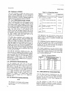
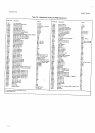
Table
7-3
lists
a
number
of symptöms
associated
with
reed
relay
failures.
7-35.
Cleanliness
of
certain
components
and
areas
of
the
AC
Converter
Assembly
are
critical
to
the
performance
of
the
AC
Voltmeter
circuits.
The
assembly
should
be
handled
only
by
the
board
extractors,
anä
should
be
cleaned
thoroughly
following
any
repair.
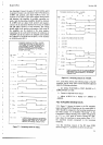
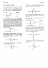
7-36.
Certain
components
on the
AC
Converter
Assem_
bly
must
be spaced
the
correct
distance
from
the printed
circuit
board
for proper
operation
of
the
circuit.
Table
74
lists
these
components
and
the proper
spacing
that
must
be
observed
during
repair.
.
Table
74.
Component
Spacing.
7-37.
OHMS
CONVERTEB
TROUBLESHOOTING.
7-38.
The
Ohms
Converter
Troubleshooting
Tree,
Fig_
ure
7-7, may
be
used
to
locate
the
trouble
if tn.
Onr
C-onverter
does not
operate
correctly.
Make
sure
the
DC
Voltmeter
operation
is
correct
before
beginnrng
the
Ohms
Converter
checks_
7-39.
The
cleanliness
of
some
areas
of
the
Ohms
C_onverter
Assembly
is
important
to
proper
operation.
Handle
the printed
circuit
board
only'by
ihe
extracton,
and
clean
the
repaired
area
thoroudily.
Table
7-3.
AC
Reed
Relay
Checks.
Ranges
Affected
Symptoms
Possible
Causes
100
v
1000
v
,IV
10v
IV
10v
100
v
ro00
v
1V
too
v
10v
r000
v
lOverload
-
1 V input
on
100 V
range
I
results
in
1 00
V display
I
I
DisOlay
is one-half
the
input
value
I
I
I
Low
input
impedance,
approx.
2O kS-t
Overload
-
I V
input
on
100
V range
results
in
5O V
disptay.
Display
is
l
/10
the
input
value
Overload
K2
Shorted
K2
open
K3
shorted
K3
open
K4
shorred
K4
open