


Section
II
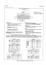
2-40.
Trigger
Connections,
GPIB 0ption 030.
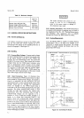
241.
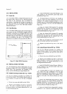
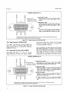
Figure 2-10 shows
the rear
panel Trigger con-
nector,
Jll,
and
lists the
External
Trigger signals. The
mating
connector
for
Jll is
-hp-
Part
No. 12514142
(Amphenol
57-30l4l).
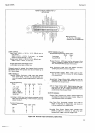
2-42.
Sample/Hold
Connections, 0ption
040/045.
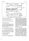
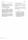
243.
Option
045.
Figure
2-ll
shows
the
external
trigger connections for Option 045,
which
is
Sample/
Model 3490A
Hold without
Option
020 or Option
030.
The
mating
connector
for Trigger Connector
Jll is
{rp-
Part No.
1 25 1 41
42
(Amphenol
57-301 4
I
).
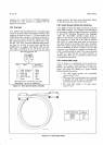
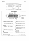
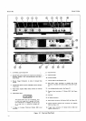
2-44. Sample/Hold
with
BCD Remote
Expand
Option
020.
When
Sample/Hold
is
included in an
instrument
with the
BCD
Remote
Expand Option
020,
the
Sample/
Hold trigger
connections
are
located
on the Remote
Input
Connector,
J7. Figure 2-6
shows
this connector
and
describes
the trigger signals.
The mating
connector
TRIGGER CONNECTOR Jl1
E
UtJJE
!2 lg
9V
=g
FCE
JF
-v
FL
L
;22399ä
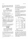
Mating Connector:
*rp- Part No.
1251.0142
Amphenol
No.57-30141
zZ
l
tr
*
Outguard
ground
is isolated from inguard
circuit common
(input
Low Terminal) and
chassis
(power
line)
ground
and
may
be
floated
a maximum of 40 V above chassis.
Sample/Hold
TTL Trigger:
LOW
input level
((+
0.4
V) for
at
least 30
nstriggers
Sample/Hold
circuits and/or
triggers 34904
to
take
a
reading.
Sample/Hold AC Trigger:
Negativegoing edge of an
input
pulse
at least 30
ns
wide and having
an
amplitude
of at
least 2 V
triggers
Sample/Hold circuits and/or
triggers
3490A
to take
a
reading.
LETF:
L
External Trigger
Flag
goes
LOW when
the
3490A
is
ready for an external
trigger, and
goes
HIGH when
trigger is received
(34904
is not looking
for
a
triggerl.
ooooo
zzzzz
6ö
E6
(9c,
t*
Figure
2-10. Trigger Connections,
GPIB
Option
030.
EA
IlJIE
\:/JIU
oclo
no(,
F=F
)
ol
F
!-
t-?
()
: HF
*o(JifC)(Jr
ui
z
z'@O zzAi
TRIGGER
CONNECTbR
Jl1
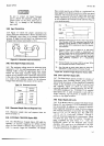
Sample/Hold TTL Trigger:
Mating Connector:
LOW
input
level
{(+
O.4
V)
for .)t least 30
ns triggers
+rp_
part
No.
1251*,142
Sample/Hold
circuits and/or
triggers 34904
to take
a
reading.
Amphenol
No.57-30141
Must
be
HIGH
at
least
60o
ps prior
to
going
Low'
Sample/Hold
AC Trigger:
Negative-going
edge
of
an
input
pulse
at
least 3()
ns wide and
having
an amplitude
of
at
least 2 V
triggers
Sample/Hold
circuits
and/or
triggers
3490A
to take a reading.
Must
be
stable
at
least
2
ps prior
to negtive transition.
Stretched
Pulse
Output:
Changes
from HIGH
l2+z.q
V)
to
LoW
({+
o.+ V)
for
a
minimum
ot
24O
tts
for
each
Sample/Hold
TTL Triggpr
or
Sample/Hold
AC Trigger
input.
The mating
connector for
Jl
1
is
*tp- Part No. 1251{142
(Amphenol
57-30141)
supplied
with
Option 045
or
Option
030.
z
l
zz
oooo
2ZZZ
--
A
ai ,4
**
*
Outguard
ground
is isolatedfrom
inguard
circuit
common
(input
Low
Terminalland
chassis
(power
linel
ground
and may be floated a maximum
of
40 V above
chassis.
Figure
2-11. Trigger Connections S/H Option
045.