


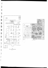
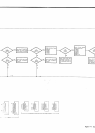
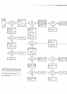
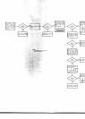

SEE
NOTE
1. Monitor
11ofAlUl2.
pin
1 of
Alt-J7.
tragger to +5
V lest
on
A1 A1. Exr
Sync,
+
Slope. Turn
3490A OFF
back ON. Voltage
at
I should remain
low
approx.
10oms, then
so
Hish
(+
5 v).
A1 U19 and A1 U21
Figure
7€, Note 1.
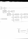
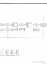
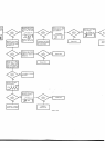
SEE NOTE
1.
Monitor
pins
and
7
of
A1 U2
';1;:-*"*-''
l+5
m
s-l
ltrl-
t'tj
,o."
1*
:lll-tl-
A't02,
A103.
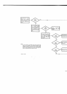
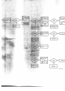
SEE NOTE
'1.
Monitor
3 of
Al U6.
Correcl
wave{orm:
I
soms
l.r-
I
-lu-lJ-
U.T:'"",'J"',l,:,t-:t
o t u u'
-+iO.254s
F
:1"/\/-\
E
NOTE 1.
Monitor
:
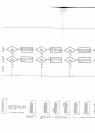
NOTE
1. M€sure
ages at
pins
1
and
4 oI
41 U4.
Both
pins
should
be
>+2.7V.
Measure
voltage at
pin
5 of
41U2.
Should be'11 V
r
to%.
Re{er
to Logic
Trouble-
shooting suggestions in PaL
agraph 7
39.
Troublesh@t
,11
V
sur
ply,
AlCR3.
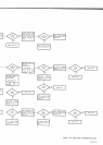
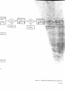
YES
YES
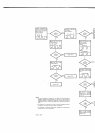
:or
waveform or
voltage, tirst
turn
3490A
OFF,
then
while
holdinq
-
TRIGGER
tlutton
depressed,
turn
instrument
ON and
measure
th!
wavetorm
or volrage.
The
pushbution
must
be held
in
while the
€nl
is taken. This
procedure
applies
only to
those tests
which
refer to
shown on Mveforms
is corred
tor
instruments
designed
for
60
Hz
rtion.
For 50
Hz instruments,
incr@se
time
by
2O%.
oscop€
is required
for
these checks.
Voltages
mV
be mesurecl
with
accuracv with
an oscillosco@.