


Section III
pose
Interface
Bus
controi,
the
3490A
should
be
programmed
for Next
External
Trigger
(T2).
When
Next
External
Trigger
is
programmed,
upon
completion
of
a
measurement
the
GPIB
circuits
wait
for
an
External
Trigger
command.
Either
of
the
Sample/Hold
Trigger
inputs
at Jll
provides
an
External
Trigger
command
to
initiate
a
measurement
at
the
same
time
a Hold
mode is
initiated.
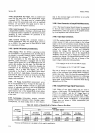
3-172. Acquisition
Time.
The
maximum
time
required
by the
DC Input
and
Sample/Hold
Amplifiers
to
respond
to
an input
voltage
varies
with
the
range
selected.
as
shown in Table
3-10.
The
acquisition
time-must
be taien
into consideration
in
Track/Hold
operation.
The
delay
incorporated
into
Acquire/Hold
operation
includes
thl
acquisition
time.
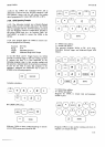
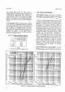
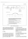
Figure
3-l
I
shows
typical
times
re_
quired
for the
amplifiers
to
respond
within
a specified
accuracy
to a
step
input
voltage.
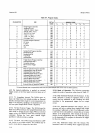
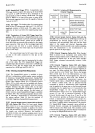
Table
3-10.
Maximum
Acquisition
(Settingl
Time
for
Full-Range
Step Input.
Model3490A
3-173.
Using
the Track/Hold
Mode.
3-174.
Digitizing
a
Ramp. The
output
of the
Sample/
Hold
amplifier
circuits
lags
the 3490|input
yoltage
by
a
delay
which
is
approximately
equal
to
" "
I
,
where
L 13dB
f:
On ir
the
3
dB
bandwidth
frequency
shown
in
Table
l-2.
When
measuring
a stable
dc input
voltage,
this
time
lag presents
no problem.
However,
if the
input
voltage
is
changing,
as a
ramp
input
for
example,
thii
delay
must
be
considered
in
interpreting
the
34gOA
reading.
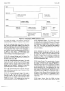
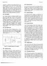
In
Track/Hold
measurements,
the
voltage
reading
is
actu_
ally
the
input
voltage
at a point
previous
to
the
time
the
Sample/Hold
Trigger
command
was
received.
The
point
of
measurement,
then,
effectively
precedes
the
trigger
command
b-y
a length
of time
equal
to
the
delay,
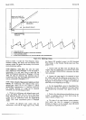
shown
in
Figure
3-12
as the
analog
dähy.
Digitization
of
a
repetitive
stable
ramp
may
be
done
as
illustrated
in
Figure
3-1
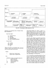
2. The
delay
between
the
start
of
the
ramp
and
the
Sample/Hold
Trigger
must
be
accurately
detei_
mined
by some
means,
such
as
an interval
timer.
It
is not
necessary
that
measurements
be made
on
successive
cycles
as
might
be
inferred
from Figure
3-12.
Measure-
ment
may
be made
on every
2nd,
3rd
or
nth
cycle
as
convenient,
if
the
waveform
is
stable.
The
maximum
dv/dt
limitations
shown
in
paragraph
3-l5g
and
Table
3{
must
be observed.
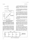
3-175.
Reoonstructing
an Input
Waveform.
An input
waveform
may
be
reconstructed
from
a
series
of
Track/Hold
measurements
by using the
second
equation
Range
Settling
Time
to
Within
0.01
% of
Final
Vatue
1V
10v
100
v
1000
v
512
tts
128
ps
512
ps
128
ps
NOTE
.1
V range
is
not
specified
(see
paragraph
3-1541.
uJ
(9
z
tr
J
J
tt
tJ-
a
=
uJ
F
at,
lrJ
o
F
J
F
=
t!
UJ
a
E
J
200
100
.lLl
.z
(r
J
J
f
IL
o
öR
=
o-
LIJ
F
.tt
Ll,
(9
F.
J
o
F
f,
=
tJ.
o
uJ
n
t-
=
o-
200
100
10
1.0
0.1
to
1.0
0.1
1
V
RANGE
6.6t
^
u.l
,,rs 1.0ps
IOps
IOOps
lms
TYPICAL
TIME
REOUIRED
TO
SETTLL
TO O.OT
X
0.o1
0.1
lrs
1.0
rrs
10,/s
100
rc
TYPICAL
TIME
REOUIRED
TO
SETTLETO
1
%
Figure
3-1
1.
Typicat
Response
to a
Step Input
Voltage.