


't
J
Model34904
tion drawing). Connect
the
gates of both
A2QIA
and B
to
ground.
Connect
a
dc
null
meter
(-hp-
419A)
between
AITPR and
ground, and adjust
AlR522
from
one
extreme
to the
other.
If
this
point adjusts
both positive
and negative, the amplifier
is
probably
operating
cor-
rectly,
and
the Bootstrap
Amplifier
should
be checked.
If AITPR will not adjust
both
positive
and
negative,
connect the dc null meter
between
the source
of A2Ql B
and
add adjust AlR522
Io
both
extremes.
The
voltage
should
adjust
both
positive
and
negative.
Each
stage
of
the
amplifier
can be
checked
in the
same
manner,
connecting the
dc
null
meter between
the
collectors
of
A1Q509A
and
B, the emitters
of
A1Q505
and AlQ508,
the
collectors of AlQ506 and AlQ507, or the
emitters
of AlQ510
and AlQ511.
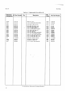
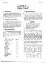
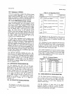
Section
VII
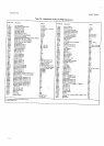
Figure
7-2.
Switching
Outputs
of A1U401.
7-21.
After
these
checks
and following
repair
of the
DC
Amplifier,
the
DC
Amp. Zero
control
should
be
adiusted
using
the
following
procedure:
a.'
Set 3490A
FUNCTION
to
TEST,
RANGE
to
2,
SAMPLE
RATE
to
FAST.
b.
Connect
a clip
lead across
A2C3.
c.
Adjust
AlR522
for
a display
of
+.000010
to
-.000026.
'l-22.
DC
Amplifier
Switching
Gircuits.
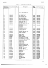
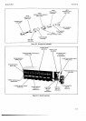
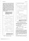
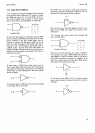
7-23. Figwe
7-l shows the
inputs
to the
DC
Amplifier
input
switching
FET's.
Waveforms
at
the
connections
to
A2U2
should
be
compared
to the
bootstrap
waveform
at
the
white
jumper
on
A2
(labeled
"Bootstrap"
on the
Component
L.ocation
drawing).
The
"OFF"
voltage
level
of
-
l7
V or
-
20 V must
be correct.
During
the
..ON"
time,
when
the
waveform
is
more
positive
than
-
17
V,
the
waveform
should
correspond to
the
bootstrap
waveform.
7-24.
The
switching
outputs
of the
DC
Logic
ROM,
shown
in Figure
7-2,
should
be as shown
in
each
case.
TRIGGER
SCOPE
AT A].TPK,
+
SLOPE.
CHECK
WAVEFORMS TO SEE
ONLY IF
.
17
V
AND. 20 V
LEVELS OCCUR AT
THECORRECTTIMES.
DURING ALL
OTHER
INTERVALS, WAVEFORMS
SHOULD COR RESPOND TO THE
BOOT.
STRAP VOLTAGE.
TIME
{ß1.
&1&til
&2
AAiGE
1 AtL
-t7v
2.5 ALt
3
0.t,1,rmr
3 to,rKV
a t@,tKv
r0
0.1,
r,10v
16
ATL
19 ATL
2I ALL
23 0_l v
TIME
SHOWN
APPLIES
TO
INSTRU.
MENTS
DESIGNED
FoR
60 Hz
LINE
OPERATION.
FoR
50
Hz INsTRU-
MENTs,
INCREASE
TIME BY
2OOIO.
TRIGGER
SCOPE AT
A1TPK,
+
SLOPE.
Alu401
6
n
lii,,,
0.1, t. t0 v
10
tt
12
13
17
t8
l9
20
21
0.1, t. 10 v
'4eoa-a'2s46
*TIME
sHowN
AppLlEs
ro TNSTRUMENTS
DESIGNED FOR
60 Hz
LINE
oPERATIoN.
FOR
50 Hz
INSTRUMENTS,
INCREASE
TIME
BY 2Oolo.
Figure
7-1
.
Switching
Inputs
to
A2U2.
t-3