


Section
III
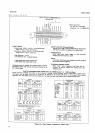
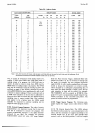
Table
3-1 .
Maximum
Voltages.
Maximum
Voltage
Between Input
HIGH and LOW
Between fi
Signal
HIGH and
LOW
Between
either
LOW
terminal
and
Guard
Between Guard
and
Chassis
100O
Vrms
250 Vrms
2O0 V
peak
500 V
peak
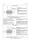
3.I 7. GENERAL
OPERATING
INSTRUCTIONS.
3-18. Turn-On
and
Warm-Up.
3-19. Before
connecting
ac
power
to
the 3490A,
make
sure the rear
panel
line selector
switches
are set to
correspond to the
voltage
of
the
available power
line
as
shown
in
Paragraph
2-5 and Figure 2-1.
3-20. Guarding.
3-21. Common-Mode
Voltages. Common-mode
voltages
are those
existing between
the power
line
ground
point
of the source
circuitry
and that
of
the
34904,
and
between the
Low
measurement point
and
power
line
ground
of the
source
circuit. When
current
due
to
these
voltages
flows into
the 3490A
input terminals, some
error in
measurement
results
because
of the voltage
drop in
the
measuring
circuit. In systems
measurements,
the resistance
of
long input
leads
may
become signifi-
cant.
Wide separation
between
the 3490A
power
line
ground
point
and
the
ground
point
of the source
circuiü,
may
result in high
common-mode
voltage.
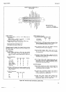
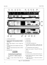
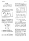
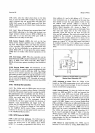
3-22.
Guard
Connection. Figure
3-2 illustrates
three
ways
of connecting
the 3490A
Guard terminal
to
reduce
errors caused
by common-mode
voltages.
In example
A,
Guard is
at
practically
the same
potential
as the
Low
measurement point,
so any common-mode
current
flows
through
Guard
and not through
the
measurement
circuit. In
example
B,
the
3490A
Guard strap
is
connected
to the
Low
terminal, placing
both
at the
same
potential.
This
allows
common-mode
current to
flow
through
the input
lead
resistance
R6, causing some
measurement
error.
This
connection
may be used if
common-mode
voltages
are
not
expected
to
be a
problem
or if
R6 is
small
(short
leads). Example
C is
similar to
A.
except
that connecting
Guard in this
manner
allows
any
common-mode
current generated
between the
Low
measurement point
and
power
line
gound
of the
source
circuit
to flow in the
measurement
circuit-
Guard
should
alwoys be connected,
either to the
Lou' terminal
or
to
a
point
in the
source
circuit
as
rrdicated.
If
the
guard
terminal
is
left open, common-
mode
voltages
may
exceed
the
Low-to-Guard
breakdown
r3ring and
damage
the
34904.
Model
3490A
The
Guard
Terminal
must
always
be
con-
nected
to
Low
or to
a corresponding
point
in the
source
circuit
or damage
to
the instrument
moy
result.
3-23.
Guarding Information.
More detailed
information
on purpose
and
methods
of
guarding
may
be found in
-hp-
Application
Note No. 123,
"Floating
Measurements
and
Guarding."
This
application note
is
available
through
your
nearest
-hp-
Sales and
Service Office.
3-24. Floating Measurements.
3-25. The
Model
3490A
is
capable
of making flöating
measurements.
That
is,
the input
Low terminal
is not
connected
to
chassis
(power
line)
ground.
The
voltage
between
the
guard
terminal
and chassis must
not
be
geater
than
500
V
peak.
r---
A. Best
Connection
-
Guard
Connected
To
Low
At
Source.
44904
--------
- -
EEST
CONNECITON
SAME VOLTAGE
NO COMMON MOOE
CURRENI
GOES
IHROUGH
Rb
9!9!'!-9 _ _ _
B.
Guard Connected To
Low At Voltmeter.
sÄME
VOLIACE
COMMON MOOE
CURRENT
6OES TBROüGH
Fb,
CAUSIN6
ERRORS
9E0!{q__
_
C. Guard
Connected To
Earth
Ground.
DOITEO
CONNECIION
DEFEAIS
GIAROI MAY
OAMACE INSIqUMENT
SOLIO
CONN€CION
SHUNTS
MUCH
OF
COMMON MOOE
CURRENT AWAY FROM
Rh,
PROVIDED
THAT
ECM
15-
MOSILY
8€TWEEN
GROUNOS
GROUNO
FLOATING
r'-
- -l
i*.J
Figure
3-2.
Connecting the Guard.