


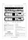

Section
III
bar
or a large
solid
copper
wire, and
adjust
AlR429
(Thermal Adj)
for
zero
display.
AlR429
is
accessible
through
the rear
panel.
If
the
3490A has
the rear
input
connector,
loosen
the
hinged
cover
to
gain
access
to
AlR429.
Be wre
to
connect
the Guard
Terminal
and
to observe
the maximum
voltage
limi-
tations
noted
on
the
front
panel
and
in
Table
3-1,
or
damage
ta the
instrument
may
rewlt.
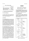
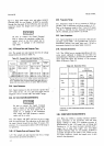
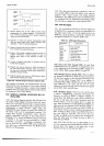
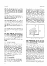
3-42.
DC Sample
Rate
and
Response
Time.
3-43.
The
sample
rate and
response
time
for dc
voltage
measurements
are
shown in
Table
3-2.
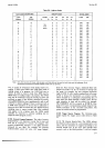
Table
3-2. Sample
Rate
and Response
Time.
*Sample
Rate Control
set to
FAST
position
and instrument
not in
overload.
Each counterclockwise
step
adds
240
ms
in
Option
050 instruments,
200
ms in
Option
060
instruments.
3-44.
Input Resistance.
345.
Input resistance
in
the dc
function
is
greater than
101
o
ohms on
the .1
V,
I V, and
10V ranges,
and
l0
megohms
t
0.1 5
7o
on
the 100
V and
1000 V
ranges.
3.46.
AC VOLTAGE
MEASUREMENTS.
Be sure
to
connect
the
Guard
Terminal
and
to observe
the maximum
voltage
limL
tations
noted
on
the
front
panel and
in
Table 3-1,
or
damage
to
the
instrument
may
result, and
high
frequency
measure-
ments
will
be
in enor-
341 .
The display
will NOT
rcad
zero
on any
ac range
with
the input shorted.
The indication
on all
ranges
with
the input
shorted should be
less
than
50 counts.
The
accuracy
of ac measurements
below
1.0%
of full
range is
not specified.
3-48.
AC
Sample
Rate and
Response
Time.
-3-49.
The sample rate and
response
time for
ac
voltage
measurements
are shown
nTable
3-2.
Model
3490A
3-50.
Frequency
Bange.
3-51.
Frequency
range
of
the ac
converter
is
20Hz
to
250kHz,
r"itft u
maximum
volt-Hertz
product
of 107.
That
is, the frequency
range
for
the
I V and
l0
V ranges
is 2OHz
to 250
kHz, but
the maximum
frequency
at
100
V
is 100 kHz,
and at
1000
V
it is
l0 kHz.
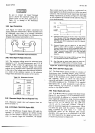
3-52.
Input lmpedance.
3-53.
Input impedance
in the
ac
function
is the
same on
all
ranges,
and
is 2 MO
t I
%
in
panllel with
(
65
pF
in
instruments
without
rear
panel input
and
(90pF
in
instruments
having
tire rear
panel
input
connector'
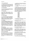
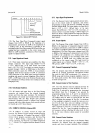
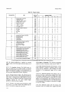
3-54.
Harmonic
D istortion.
3-55.
The
3490A
has an average-responding
ac-dc
con-
verter
circuit
calibrated
to display
the rms
value
of a
sinusoidal
input.
Therefore,
any
distortion
present in the
input
signal
will affect
the accuracy
of the
measure-
ments
as shown
in Table
3-3.
Table 3-3.
Distortion
Error.
Harmonic
%
Distortion
Yo Error
{*Fundamental)
Max.
Positive
Max.
Negativr
Any
even
o.1
0.5
1.0
2.O
0.000
0.001
0.005
0.020
Third
0.1
o.5
1.0
2.o
o.033
0.1
68
0.338
0.687
0.003
o.167
0.328
0.667
Fifth
0.1
o.5
1.0
2.O
0.020
0.1 01
0.205
o.420
0.020
o.099
0.195
1.380
*Depends
on
phase
relationship
between
harmonic and
fundamental.
3.56.
RESISTANCE
MEASUREMENTS.
3-57.
When the
3490A
is making
resistance
measure-
ments,
movement
of the
instruction
card
will
cause
display
readings
to
jump.
For
optimum
accuracy
of
mtusur.*ents
on
the .1
kO
range'
first
set
Range
and
Function
to
.1V
dc, short
the
input
terminals
with
a
copper
bar
or
large
solid
copper
wire, and
adjust
efn+zq
(Thermal
Adj)
for
zero
display'
A1R429
is
accessible
through
the
rear
panel.
If the
3490A
has
the
rear
input
connector,
loosen
the hinged
cover
to
gain
access
to
the adiustment.
Function
Minimum Sample
Period*
Response
Time
Option
050
Option
O60
DC
Volts
AC
Volts
Ohms
.1
k thru
100
ko
1,O00
kf,,
10,000
ko
240.2ms+5ms
1.26s+.025s
240.2ms+5ms
300.2ms+6ms
660.3
ms
+
12 ms
200.1
ms+4ms
1.05s+.025s
200.1
ms+4ms
250.1
ms+5ms
550.2
ms
+
l0
ms
200.1
ms
1.05 s
2OO.1
ms
25O.1
ms
550.2
ms