


Model3490A
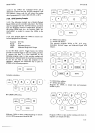
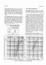
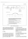
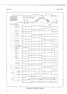
The step
input
voltage
must
remain stable
for
at
least
the
duration
of the
Acquire/Hold
aperature time
shown
in
Table 1-2.
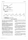
3181.
Measuring
Pulse
Height.
hcquire/Hold
may
be
used to measure
the
height
of a
pulse
or square
wave.
The
width of the
pulse (or
one-half
of the
square
wave)
must
be
greater
than the
aperture time shown
in
Table
l-2. Triggering
may
be applied
coincident
with the
leading
edge
of each input
pulse.
3-182.
Using
50
Hz
or
60
Hz
Power
Source
(Options
050
or 060).
3-183.
The
3490A
has
the capability
of operating
from
a
50
Hz or
60
Hz
power
source.
Option
050 is
available
for
50
Hz
operation
and consists
of using
a 3.333 MHz
crystal
(Y2)
in
the clock
and AlR207
=
100 kSr.
Option
060 provides
for
60 Hz
operation
and
uses
a 4 MHz crys-
tal
CYI)
in
the
clock
and
AlR207
=
84.5 kQ.
See Table
2-1.
$184.
RATIO
lf'leasurements
(0ption
080).
3185.
Instructions
for
making ratio
measurements
with
the
Model
3490A,
Option
080,
are contained in the
following
paragaphs.
DC-to-dc
and
ac-to-dc
..three-
wire"
ratio
measurements
can
be made; that is, the
EXT
REF
input
Low
terminal
and the
INPUT
Low terminal
are connected
intemally.
Because
the same
terminals
are
used
for
Ohms
measurements
and for Ratio
measure-
ments,
these
two
functions
are
mutually exclusive.
$186.
External
Beference
Voltages.
3187.
The
front
panel
Ratio
switch selects
either the
lntemal
Reference
or the
I
V or l0
V External
Refer-
ence
range.
If
the
I V
range
is
selected, the
external
Section
III
3-1 92. Ratio
Measrement
Procedure.
a.
Set RATIO
switch
to I V or
l0 V EXT
REF
range.
If the
external
reference
voltage is between
1.0
V
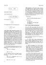
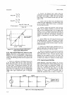
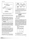
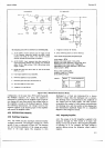
Figure 3-16. Ratio Input
Connections.
reference
voltage
may
be either
a
positive
or negative
voltage
between
0.1
V
and
1.2Y.
On
the
l0 V
range,
the
reference
may
be
positive
or negative,
I
V
to
l2
V.
3-188. lnput
Connections
3-189.
The
dc external
reference
and unknown
input
voltage
should
be
connected
as shown in
Fizure
3-16.
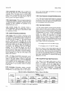
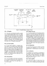
External
Reference
I
nput
I
nput
Signal
Displayed
Polarity
+
+
+
+
+
ac
ac
+
+
none
none
Extemal
Reference
Low
and
Input
Low
must
be
at the same
potential;
these ter-
minals
are connected
intemally.
Connect
Guard
to Input
Low.
3-190.
Ratio Display.
3-191.
Ifthe I
V External
Reference
range
is selected,
the
display
reads
the
ratio
directly,
but if the 10
V
reference
range is
used, multiply the
display by
0.1.
In
dc/dc
ratio
measurements,
the polarity
symbol
is
+
vshsn
the
external
reference
and input voltages
are the
same
polarity,
and
-
if they
are opposite in
polarity (see
Table
3-ll).
In
ac/dc
measurements,
no polarity
symbol
is
displayed.
Any
ratio
measurement
is limited
to l2O
%
of
the
input
range selected.
If
autoranging
is selected,
'upranging
occurs
at
l2O
%
of
rcnge
and downranging
at
lO%
of
range.
Overload indication
is the
same
as
in
voltage
measurements.
Table
3-11.
Ratio Polarity
Display.
STEP INPUT
-
FULL
SCALE
SAMPLE/HOLD
TRIGGER
APERTURE
TIME
>
ACOUISITION
TIME
Figure
3-15. Measurement
of a
Step
Input.
tu
3-21