


Section III
3-149.
Sample/Hold
AC Trigger. This
ac
coupled
com-
mand
has the
same
effect
as the
Sample/Hold
Trigger
command
(TTL).
This signal
must
be a negative-going
pulse
at least 30 nanoseconds
wide
with
an
amplitude
between
2Y and 200
V.
The signal
must
be static
at
least
2
ps prior
to the negative transition.
3-150.
Hold
Command.
This
is
an intemal
command
to
a
Sample/Hold
amplifier,
resulting
in
a Hold
mode.
Hold
A command
switches
Amplifier
A and
Hold
B switches
Amplifier
B. Both commands
are generated
in the
Sample/Hold
logic
circuits.
3-151. External
Encode.
This command
initiates
a
3490A
measurement
when the
Sample Rate
control
is
set to HOLD.
This
signal
must
be
from HIGH
to
LOW
for
a minimum
of
240
ps.
3-152. Special
S/H 0perating
Gonsiderations.
3-153. Display. When
the 3490A
is
operating in
either
the Track/Hold
or
Acquire/Hold
mode, the
fifth
digit in
the
display is
normally
blanked,
leaving
a
display of 4
full
digits
plus
the
overrange
"1".
This
is
done
because
of the
uncertainty
in
the
fifth
digit
due to
noise.
However,
if the
instrument
is
equipped
with the
Data
Output
(BCD)
Option
021 or the
GPIB
Option
030, the
output
data
includes
the
fifth
digit.
The
fifth
digit can
be restored
to
the
display
if
desired
by
changing
the
connection
of
the
white/black
wire
from the
display
assembly.
For
a
4
-
digit
S/H display,
this
wire
is
connected
to Test
Point
L on the
Main
Circuit
Assem-
bly,
Al,
and
for
a
5
-
digit
display, it
should
be moved to
Test
Point
M.
These
test points
are
located
on the
Main
Circuit
Assembly
just
to
the rear
of P2,
which is
the
display
cable
connector.
-._"
3-154.
.1 V
Range.
Sample/Hold
measurement
accur-
acy is not
specified
for the
.l V range.
On
this
range,
the
output
of
the Input
amplifier
contains
an appreciable
amount
of wideband
noise
due to the
broad
bandwidth
of
the
amplifier
and
the
amplifier
gain
of
X100. The
rapid
response
time
of the
Sample/Hold
circuits
allows
the
Hold
mode
to
occur
anywhere
rvithin
the
envelope
of
the noise-
3-155.
Autoranging.
Autoranging
requires
successive
readings (initiated
internally)
when
changing
ranges.
Consequently,
the
final
reading
loses
its time
relation-
Model34904
ship to
the extemal
trigger
and
therefore
is
not
useful
Sample/Hold
information.
3-156. Guard
Connection
in
Sample/Hold Meaurements.
3-157.
The
Guard terminal
should
always be
connected
to
the
Low input
terminal
when making
Sample/Hold
measurements,
unless
the
guard
can be
properly
driven
by a low-impedance
and low-noise
source.
3-158.
Input
Signal Limitations.
3-1 59.The
analog-to-digital
conversion process
requires
a
certain
amount of time,
and any change in the
voltage
input
to the A-to-D
conversion
circuits during this
time
degrades
the
accuracy of the
measurement. The purpose
of
Sample/Hold
is to
"fresze",
or hold, a changing
input
voltage
at a specific
point
in
time
and
accurately
measure the voltage.
The
bandwidth
of the Input
Amplifier
and the
response time
of
the
Sample/Hold
Amplifiers
restrict the
rate at which the
voltage to
be
measured can
change. The
Sample/Hold circuits
are able
to
maintain tracking
only if the
rate of change
of the
input voltage
is within the
follo,wing limits:
2.5
%rangelps
on the
l0 V and 1000
V ranges.
5
%
of
rmgelps on the I
V and 100 V
ranges.
The
rate of change
in
input
voltage
(dv/dt)
affects the
ability
of
the
instrument
with
SampleiHold
to
digitize
a
ramp
or sine
wave.
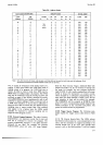
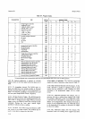
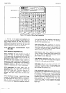
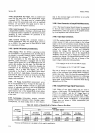
Table 3-8
shows the
maximum
dV/dt
for a ramp
and
the
maximum
frequency
for
a full-range
sine
wave
to
be measured
within the
accruacy
given.
The
input signal
is
also limited to
a maximum
dV/dt
during
digitization
of 50 V/ss.
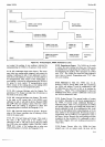
3-160. Sample/Hold Trigger
Signal
Requirements.
3-161.
Either
of two signal
inputs
may
be used
to
initiate a
Hold mode. The
Sample/Hold Trigger
input
(TTL)
is
dc
coupled,
and the AC
Trigger
input,
of
course,
is ac coupled.
The
term
"Sample/Hold
Trigger"
is
used
as
a
general
term
in this
manual to
refer to either
signal.
tn
some option
combinations,
a
Sample/Hold
Trigger
does not initiate
a 3490A measurement
(see
Paragraph
3-165).
Table
3-8. Ability
of
Sample/Hotd
to
Digitize
a Ramp
or
Sine Wave.
Acc|Jracy*
(%
of
Rangef
BANGE
10v
1 V,
100
V,
1000
v
Ramp
Sine Wave
lZero
Crossing)
Sine Wave
(Peak
Reading)
Ramp
Sine Waw
(Zero
Crossing)
Sine Wave
{Peak
Reading)
.01
%
30 v/s
5Hz
75O
Hz
12.5
V
lS 2Hz
3OO Hz
1%
300
v/s
5O
Hz
275O
Hz
125 V/S
20 Hz
90O
Hz
1%
3000
v/s
5O0 Hz
75OO
Hz
1250 V/S
2OO Hz
3ü)O Hz
*Accuracy
specifications
are
to
be added
to
(%
of range)
dc specification.
-1-l o