


Model3490A
Trigger
Enable
signal
HIGH,
inhibiting any
further
Sample/Hold
Trigger
pulses for the duration
of the
measurement
sequence.
A measurement may
also be
initiated
internally
by
the Intemal
Hold
Command signal
if the
3490A
is operating
in
the
automatic sampling
mode,
or
if triggered
by
the front
panel pushbutton.
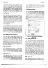
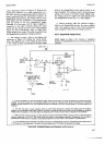
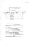
+235. Read
Only
Memory.
A
microcircuit
Read
Only
Memory
(ROM) is
the central component
of the
Sample/Hold
Logic
control
circuits.
Six memory
inputs
in the
"present"
state, along with
two
"qualifier"
inputs,
determine
the next
state of
the
ROM. In
each
state, the
ROM
provides the
proper
outputs
to
determine the
next
step
to
be
taken
in the
Sample/Hold
measurement
sequence.
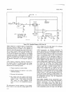
+236.
State
and Memory
Storage. The
State Storage
circuits are
cleared
when
the 3490A
is
first tumed
on.
so
that
all
six
of
the
State Storage outputs
are
LOW. Two
of
the next state
outputs
are
stored
in
D Flip-Flops
which are
clocked
by the
positive-going
edge
of the
clock signal, HSHC.
The other four
next state
outputs
are stored in a selectable
input
storage
unit,
which is
clocked
by
the
negative-going
edge
ofthe
inverted
clock
sigral,
LSHC. Consequently,
all
six
ROM next
state
outputs
are clocked
into storage
at the same
time,
because HSHC
and
LSHC are
opposite in phase.
The two
qualifier
inputs,
as well
as
the
control
signal
outputs
from the
ROM,
are clocked
into
memory storage
by
the
negative-going
edge
of the
clock signal,
HSHC. By this
method,
all
state
storage
circuits
are clocked
at one
time,
and
all
memory
storage
circuits
are clocked
at another
time.
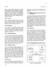
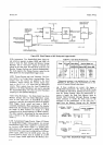
4-23!.
Oualifier
Multiplexers.
The
two
qualifier
inputs
t9
the
ROM,
along
with
the six present-state
inputs,
determine
the
next-state
outputs
from
the
ROM. These
qualifier
inputs
are
selected
by two
8line to lline
multiplexers.
Selection
is
determined
bv
three
of the
Section
IV
present-state
outputs
from
State
Storage FIPA,
HpB
and
HPC.
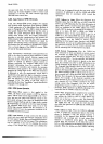
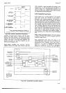
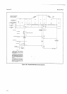
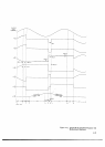
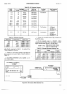
ut-238.
Sample/Hold
Measurement
Sequence. The
tim-
ing sequence
for
a Sample/Hold
measurement
is
shown
in Figure
4-30. The
states
of
Main Time
Bits
C,
B
and A
must
be
modified
for
Sample/Hold
measurements
in
order
for the
circuits
to track
the input
voltage between
measurements.
The states
of
these signals
for the
various
portions
of the
measurement
cycle
are
shown
in the
upper part
of Figure
4-30.
The
states shown
for
a normal
measurement
(not
Sample/Hold)
are
the states
of these
signals
as
received
by
the
Sample/Hold
logic circuits.
The
state
sequence
for
a Sample/Hold
measurement
is then
modified
as shown.
During
a normal
measurement (with
Sample/Hold in the
3490A),
the timing
bit sequence
is
not
modified;
however,
there
is
a delay
in
the
Storage
circuit
equal
to
the
duration
of one
cycle
of the
Sample/Hold
State Clock.
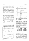
zl-239.
Reference
Polarity
Logic.
In
Sample/Hold
mea-
surements,
the
3490A
input
signal
is inverted
in
the
Sample/Hold
amplifiers.
Consequently,
the polarity
in-
formation
derived
from
the Integrator
is incorrect.
The
logic level
of the
polarity
signal
must be inverted
to
supply
the
correct
display polarity
and to select
the
proper
reference
voltage
for run-down.
This
is
accom-
plished
by an
Exclusive
OR
gate
and an inverter.
The
gate
output is
HIGH
if
one and
only one
of its inputs
is
HIGH.
If
both
inputs
are either
HIGH
or
LOW, the
output
is
LOW.
In
Sample/Hold
measurements,
one
input
to
the
gate
is
always
LOW, so its
output
follows
the polarity
signal
at
the
other input. The gate
output
is
then
inverted
and
becomes the
Display
Polarity
signal.
When
Sample/Hold
operation
is not
selected,
one
input
to
the
Exclusive
OR
gate
is
not
always HIGH.
The
polarity
signal
at
the
other input
is
then inverted
by
both the gate
and
the
inverter;
consequently,
the
logic
level
of the
Display
Polarity
signal
is the
same
as
the
..Ratio
Polarity
signal
at the gate
input.
4-27