


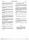

Model3490A
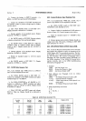
d.
Check
other
power
supply
voltages by
connecting
digital
voltmeter
and
oscilloscope
to test
points
listed in
Table
5-9. If any
voltage
is not
correct,
refer to Section
vu.
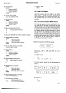
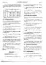
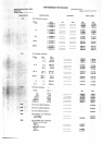
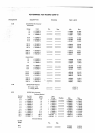
Table
5-9.
Power SUPPIY
Voltages.
A1A1
Test
Point
Voltage
Ripple*
+
17\l
+
5V
+30V
-
17V
-
5V
-
30v
+
16.99
to
+
17.01 V
+
4.995 to
+
5.075 V
+
30.10
to
+
30.90
V
-
16.9
to
-
17.1
V
-
5.00
to
-
5.85 V
-
30.10
to- 30.90V
<
50
mV
p-p
<
60
mV
p-p
(
25
mV
p-p
< 50 mV
p-p
(60mVpp
(25mVp{
*All
ripple
measurements are with the
Sample
Rate
on
HOLD.
5.55.
DC
ZERO ADJUSTMENTS.
5-56. A dc standard
(-hp-
7a0B)
and
a
dc voltmeter
able
to
resolve
l0
pV
are
required for
these
adjustments.
a. Connect
dc
voltmeter
between
AlAl
test
point
A
and
input
Low
terminal.
b. S€t
3490A
SAMPLE
RATE control
fully
counter-
clockwise to
HOLD
position.
c. Adjust AlAlR2l0
(lntZero)
for voltmeter
read-
ing
of 0
r 150 gV.
Disconnect
voltmeter.
d.
Set
FUNCTION
to
DC.
RANGE to
l0
V. SAM-
PLE
RATE
to
FAST.
e.
Connect
dc standard
to
3490A input
and adjust
standard
output
to
+
0.00100 V.
f. Adjust
AlAlR225 (Zero
DetecI
kvel) for maxi-
mum
reading
on
3490A
display. Note
reading.
C.
Reverse
polarity
of
input
and adjust AlAlR228
(Tumover)
for
reading
noted
in step
f.
Continue
reversing
input
polarity
and
adjusting
AlAlR228 until
positive
and negative
readings
are equal.
h.
Apply
+
0.00100
V input
to
3490A.
Adjust
AlAlR225 (Zero
Detect
kvel)
for
3490A
display of
+
00.0010.
$57. REFERENCE
ADJUSTMENTS.
5-58.
A
dc standard
(hp-
7a0B)
is
required for these
adjustments.
Guqrd Terminal
should
be
connected
to Low
or damage
to
the
instrument
may result.
a.
Set 3490A
FUNCTION
to
DC.
RANGE to t0 V.
AOJUSTMENT
PROCEDURES
Section
V
b.
Connect
dc
standard
to
3490A
input
and
adjust
standard
output to
-
10.0000
v.
c. Adjust
AlAlR3ll
(+Ref)
for
3490A
display
of
-
10.0000.
d.
Set
3490A
FUNCTION
to
TEST,
RANGE
to
3.
Adjust
AlA1R3l7
(-
REF)
so
that
positive
and negative
display
readings
are equal
within I
count.
Last
digit
must
be
between
2 and
9
(0.9999x).
If
not,
repeat
steps
a through
d. Dsconnect
dc
standard.
5.59. DC
AMPLIFIER
ADJUSTMENTS.
560.
A
dc standard
(hp-
7a0B) is
required
for
these
adjustments.
a.
Set
349OA
FUNCTION
to
DC, RANGE
to .l V.
Short input
terminals
with
a
copper
bar or
heavy
solid
copper
wire.
b. Adjust
AlR429,
accessible
through
hole in
rear
panel,
for
3490A display
of
0
r
.000002.
c.
Set
3490A
RANGE to
I V.
d. Remove
short from
input terminals
and
connect
dc standard. Adjust
standard
output
to
-
1.000000
V.
e. Adjust
A2Rl5
(l
V
Adj) for 3490A
display
of
-
1.00000.
f.
Set 3490A
RANGE to 100
V,
and
adjust
dc
standard
output to
-
100.000
V.
g.
Adjust
A2R3
(100
V
Adj) for 3490A
display
of
-
100.000.
Reduce
dc
standard
output
and disconnect.
h.
Set
3490A
FUNCTION
to TEST,
RANGE
to
6.
Short input terminals
and note
amount
and
polarity
of
oTfset
reading.
i.
Remove short
and
apply
-
10.0000
V input.
Adjust
A2Rl6 (0.1
V
Adj) for
display of
-
1000.00,
minus
(algebraically
subtracting)
the
offset noted in
step
h.
$6I. AC
CONVERTER
ADJUSTMENTS.
5-62. Adjustment
of the
dc circuits, Paragraphs
5-53
through
5-60, must
be completed
before
beginning
this
procedure.
An
ac calibrator
(-hp-
745A) with
a correc-
tion
factor chart
is required
for these
adjustments.
Guard
covers must
be in
place
for this
procedure.
5-63. I
V Range Adjustments.
a.
Set
3490A
FTINCTION
to
AC. RANGE to
I V.
b. Connect
ac calibrator
to 3490A input.
Set
calibra-
tor
output to
I
.000000 V
at
100
kHz
(using
correction
factor
chart
as necessary).
s-l 5