


Model
3490A
3-26.
0verrange
Measürements.
3-27. Measwements
within
rated
accuracy
are
possible
up
to 120
7o
of runge
on all except the
1000
Vac
or
dc
ranges. Overrange
inputs on
these
ranges
would
exceed
the maximum
allowable
input
voltage.
The
display
includes the overrange
"1"
as
the sixth
digit.
3-28. Overload
Indication.
3-29. lf the
measurement
is 120
%
of
nnge
or
geater,
the
Overload
"OL"
annunciator will
light.
The
numerical
display will read
120000 to 120005.
3-30.
Bange
Indication.
3-31.
The 349OA
display always
reads
in volts
or
kilohms
(except
in
Ratio
measurements),
with the
decimal
point
and
range switch
indicating
the
range
selected. In
autorange
mode, the
decimal point
alone
indicates
range.
3-32.
Function Indication.
3-33.
In the standard
3490A,
function is
indicated
only
by the function
switch position.
If
optional
Remote
control
is in use,
the
"REM"
annunciator
lights
to
indicate
that the
front
panel
switches
are
disabled. An
available
special
display
assembly
adds V,
AC,
Kfl
and
TST
annunciators
to
indicate
the
function
selected.
3-34.
Autoranging.
3-35.
In
the autorange
mode,
upranging
occurs at l2O%
of
range and
downranglng
at
lOVo
of
range. Ameasure-
ment sequence
is
not
completed
unless the
reading
is
on
the proper
range.
For
example,
if
the
Sample
Rate
control
is set
to
Hold
and the
Manual Trigger
push-
button
depressed
once,
the 3490A
will continue
to
sample
until
one
reading
is
taken
on
the correct
range.
When
the
3490A
is
changed
to the
autorange
mode
from
a voltage
range,
the
first
reading
in
autorange
is not
valid.
3-36.
ManualTrigger.
3-37.
Manual
triggering
is
available
on
all
instruments.
When
the
Sample
Rate
control
is set to
Hold,
one
measurement
results
each
time
the Manual pushbutton
is
depressed.
If
the
pushbutton
is
depressed
while the
instrument
is
not
in
the
Hold
condition,
automatic
sampling
will stop
until
the
button
is released.
3.38.
SELF.TEST
OPERATION.
3-39.
The
Intemal
Test
function
of
the 3490A
verifies
proper
operation
of
most
of the
dc
circuits,
logic
circuits,
and
the
ohmmeter
reference.
Use
the
following
procedure
to perform
the
Intemal
Tests.
If
Test
No. I
ii
not
correct,
refer
to
the
Troubleshootingsection.
Ifany
of the
other
tests
are
not
correct,
refei to
the
perfoi_
mance
Checks.
Section
III
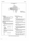
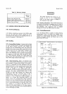
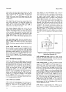
a.
Set
Function
to TEST.
If
instrument
has
Ratio
or
Sample/Hold
options,
set
RATIO
to
INT
REF
and
SAMPLE/HOLD
to
OFF.
b.
Set
SAMPLE
RATE
control
one position
clock-
wise from
HOLD.
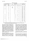
c.
Select
RANGE
l,
which
is
Logic
Test.
The
display
should
_follow
the
sequence
below,
starting
at
any point
in
the
list.
All
readings
should
be
in
the
order
ih-own,
with
the polarity
sign,
numbers,
and
decimal
points
ai
shown.
The
last
reading
listed
displays
all
digiis
as
the
count
accumulates,
then
stops
at the
number
shown.
The,last
two
digits in
the last
number
are not
significant
to
the
test.
If
these
displays
are correct,
most
of the
logic
circuits
are
operating
correctly.
+
080.024
+
o4.oo24
+
0.20024
+
.0too24
+
0.09032
+
to.oo24
+
200.024
+
4000.24
+
80002.4
+
6000.xx
OL
d.
Select
RANGE
2.
The
display should
be .000000
t
2 counts.
This
verifies
the
l0
V range
zero.
e.
Select
RANGE
3.
Difference
between
+
and
-
readings
should
be
(8
counts.
f.
Select
RANGE
4.
Using
a
dc standard
having
an
accuracy
of t
0.01
% or better,
apply
an
input
of
-
10.0000
V. Display
should
be
+
09.9990
+
(16
counts
+
dc standard
error).
This
checks
the
+
Reference.
Ifthe
3490A
has the
ratio
option,
set
RATIO to
EXT
REF
l0 V
and short
EXT
REF
input
terminals.
Display
shoüld
be r
00.0000.
This
checks the
Ratio
Reference
dmplifier
zero.
Return
RATIO
switch
to INT
REF
position
and
remove
short
from
input.
g.
Select RANGE
5. Display
should
be
000.000 t
t5
'counts,
verifying
the
0.1 V range
zero.
h.
Select
RANGE
6. Using
a dc standard
having
an
accuracy
of t
0.01
% or better,
apply
an input
of
-
10.0000V.
Display
should
be
-
1000.00
I
(35
counts
+
dc standard
error).
This
ehecks
the
dc input
0.01
attenuation
and
the dc
amplifier
xl00
gain.
i.
Select
RANGE
7.
Short fl
SIGNAL
terminals.
Dsplay
should
be
-
09700.0 1
7000 counts.
This
verifies
proper
operation
of the
Ohms
Converter.
3-40. DC
VOLTAGE
MEASUREMENTS.
341.
For
optimum
accuracy
of measurements
on
the
.l V
range,
first
short
the
input
terminals
with
a
copper
J-J