


Section IV
Model3490A
EXTERML
REFERENCE
AMPLIFIER
EXT
REF
INPUT
BIAS
CURRENT
+
TO
+REF
FET
A?U?F
t
I
COMPENSATING
CURRENT
90K
toK
VOLTAGE
=
INPUT VOLTAGE
34904-
B
-
3044
INPUT
COMPENSATION
AMPLIFIER
VOLTAGE
AT
976K
AMP INPUTS
APPROX EQUAL
+
l7v
FEEDBACK
AMPLIFIER
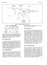
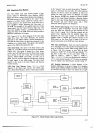
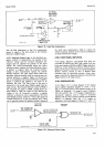
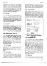
Figure
4-15.
Input Bias
Compensation.
with
the
Bias Adjustment
so
that
the compensating
current
is
equal
to
the bias
current at
the
External
Reference
Amplifier
inPut.
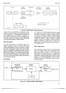
4-127. Reference
Polarity
Logic.
In
the
dual-slope
inte-
gration method
of measurement,
the
polarity of
the
reference
voltage
used for run-down
(integrator
dis
charge) must
be opposite
the
polarity
of
the input
voltage.
The
3490A
automatically
selects the correct
reference
polarity
whether the
External Reference
input
is
positive
or
negative. Since
the external reference
voltage
in ratio measurements
replaces
the
positive
internal reference,
the logic
signal which
selects the
rundown reference
polarity
must be
inverted when
the
extemal
reference
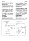
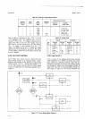
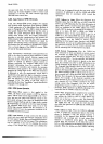
is negative. Figure
4-16 shows how
this is
accomplished.
The External Reference
Amplifier
output is inverted
and
applied to
one input of an
Exclusive
OR Gate.
The other
input of this
gate
is
connected to the stored
Input Polarity signal from
the
I"ogic
circuits.
The Exclusive OR Gate
output is HIGH if
one
and only one input is HIGH.
If both
inputs
are
either
HIGH
or LOW, the output
is
LOW. Because
the
output
of
the
AC Converter
is
positive, a
negative
reference
is selected
in all ac measurements.
The front
panel
display polarity
symbol is
+
if the input signal and
extemal
reference
are of
the same
polarity,
and
-
if they
are of
opposite polarity.
No
polarity symbol
is
displayed
for acldc
ratio measurements.
Table
4-2 shows
the
reference
polarity
required
for
the various
combinations
of
input
and reference
voltages.
+128.
FBONT
PANEL S1VITCHING.
4-129. Range,
Function,
and Sample
Rate delay are
controlled
by HIGH
true
BCD
logic signals
from the
front
panel switches. HOLD and
MAN
Trigger
signals
are
LOW
true.
If
the
3490A
has
a
Remote
Control
option,
Range
and
Function
information are
routed
through
the
Remote
Control
circuits
so
that,
if desired,
these
operations
may be
controlled
remotely.
Unless Auto-
range
is selected,
the Range
information
is stored by
the
Range Counter
in the Logic
circuits.
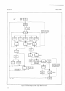
4130.
POWER
SUPPLIES.
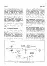
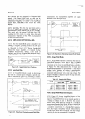
4-131.
Figure
4-17
is
a block
diagram
of
the
inguard
power
supplies.
Regulated
supplies
of
t 30
V,
t
17 V,
'änd
t 5
V
provide power to the
inguard
circuits of
the
"
3490A.
An
outguard
+
5
V
supply
is
a
part
of Options
O2O, O2l
andO22.
The
+
17V supply
is
regulated
by
a
microcircuit
regulator,
and
its output
is accurately
adjusted.
All the other
inguard
regulator
circuits depend
directly
or indirectly
upon the
+
l7 V
supply, as
indicated
in
the
block
diagram
of
Figure
4-17,
since
+
l7
INVERTING
AMPLIFIER
+
FOR
+
EXTERNAL
REF.
.
FOR
.
EXTERNAL REF.
+
FOR INTERNAL REF.
LOW FOR
+
EXTERNAL
REF.
HIGH FOR
.
EXTERNAL
REF.
LOW FOR
INTERNAL
REF.
RATIO
POLARITY
(SEE
TABLE
4-1)
,
I
HtGH
FOR
+
tNpUT
LOW
FOR
.
INPUT
HIGH
FOR AC INPUT
Figure
4-16. Reference
Polarity
Logic.
+t5