


Section VII
b. If the
problem
is not
with
an option,
determine
if
the
faulty
supply
is
in current limit
(see
Paragraph
7-12).
If
so, determine where
the
short is
by use of the
power
supply
jumpers
and
troubleshoot
that section.
c.
If
the faulty supply
is not
in
cunent limit,
determine if the faulty supply has
the correct
raw
supply
voltage (see
Table 7-l). ß the
raw
supply
does not
meet
specification,
troubleshoot this
section.
d. If
the faulty supply
is not in
current
limit
and the
raw
supply
is within
specification,
troubleshoot
the
faulty
supply.
7-11.
lf
the
+
17
V
supply
is out
of specification
and
cannot
be adjusted
per
Paragraph
5-54,
troubleshoot
according to
Paragraph
7-10,
steps a,
b,
c
and
d.
It
is
essential that the
+
17 V supply
be within
specification
since all other
supplies
are
referenced
to
this supply
and
will be affected. If
oscillation
problems
are encountered
on the
+l1Y
supply,
change
AlClOg to
1000pF,
400
pF
or remove
from
circuit.
If there
are ripple
problems
on
the
+
17 Y supply
or any
other
supply,
check to assure
the line voltage
selection
switches
are set
to correspond
with
available line
voltage.
If ripple
still
exists, replace
the
filter
capacitor
of faulty
supply.
Ripple problems
on
the
-
17 V supply
can
be caused
by
ripple or low
voltage
of the
-
30
V supply
Qower
voltage
than the
-24Y
raw
voltage supply).
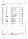
1-12.
Nl
power
supply
regulators
are
current
limited
so
that if
an
excessive
load is
applied, the regulator
voltage
output
goes
to neat
zero. If
this is suspected to
be the
problem,
the
supply
in current limiting
can
be deter-
mined
by measuring
for the current
limit voltage
across
the resistor
which are
both specified
in Table
7-1.
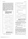
Provision
has
been
made for isolating
certain
areas
of
tfue
Main
Circuit Assembly
by removing
designated
jump6r
wires in order
to
locate
the area
where
excessive
loading
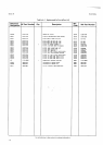
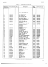
occurs.
Table
7-2 lists
the
jumper
wire designations
and
the
circuits
supplied
through each.
These
jumpers
are
located
on
the
Main
Circuit Assembly,
Al
and the
vertical
board,
AlAl.
All of
the
Logic
circuits
are
supplied
through
only one
jumper
wire for each
voltage.
Consequently,
jumper
wires are
provided
in the
ground
circuits
to isolated portions
of the logic
circuits.
These
ground
jumpers
are
shown on the schematic
diagrams,
Figure
7-23
andT-24.
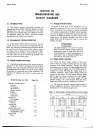
7.13.
DC
ANAL0c
CtRCUtTS.
7-14.
The DC
Analog
Troubleshooting
Tree, Figure
7-5,
covers
the
DC
Amplifier,
Integrator
and Zeto
Detect
circuits,
I
l0
V
References,
the
DC
Switching Logic
and
kvel
Translators
and
the Power
Supplies.
7-15.
AZ
Asembly
Exchange.
7-16.
Cleanliness
of the
A2
High
Impedance
Assembly
and
the proper
positioning
of
components
on
the
assembly
are
highly
important
to the performance
of the
instrument.
Also,
A2U2
is
very
difficult to
replace.
Consequently,
a rebuilt
High Impedance
Assembly,
-hp-
Part
No.
03490-69502,
has
been
made
available to
Model
3490A
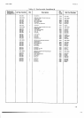
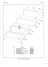
TableT-2.
Power
Supply Jumper Wires.
Voltag€
Wire Location
Circuits Supplied
+17V
+17V
+17V
-17V
-17
V
-17
V
-17V
+30V
+30V
+30V
-30v
-30v
-30v
+5
+5
+5
-5V
-5V
WH
w2
W6
wl
WEE
W3
ua
wz
WBB
W4
WAA
wcc
WFF
W7
WG
W5
WJ
W1
A1
A1A1
A1A1
A1
AI
A1A1
AlAT
AI
A1
A1A1
A1
A,'41
A1A1
A1
AlA.I
A1
A1
A1
Logic
t
10
V Reference
Integrator,
Zero Detect
logic
DC
Switching
Level
Translators
tl0
V Reference
Integrator,
Zero Detect
Integrator,
Zero Detect
DC Amplifier
t
10 V Reference
Integrator, Zero Detect
DC Amplifier
DC Switching Level Translators.
A1CR403
Logic, Display,
Switches
Al U4Ol
,
O\rerload Protection,
DC
Switching Logic
Integrator, Zero Detect
Logic
Integrator, Zero
Detect.
facilitate
repair of
your
3490A when the
trouble is
on
the A2 Assembly.
Contact
your
nearest
-hp-
Sales and
Service
Office for
details.
7-17. DC Amplifier
Checks.
7-18.
To
check the
DC
Amplifier zero, set the
Function
switch
to
TEST
and select
Range
5.
This
grounds
the
amplifier input and sets
the
amplifier
gain
to
100. The
front
panel
display
should
be
000.000
1
15
counts.
To
check
for
leakage current
in the
input circuits,
compare
the numerical
reading in Test
5 to the
reading in
Test
6
with the input
terminals shorted.
lf
the reading in
lest
6
is
sömewhat higher
(igroring
the decimal point),
check
for leakage current.
Remember
that
no soldering
should
be done on
the
A2 Assembly (see
Paragraph
7-14).
7-19.
If
the
DC
Amplifier
cannot
be adjusted to
zero in
Paragaph 5-60
step
b, it is possible
that there
may
be
leakage
to Guard
from
some point
in the circuits.
Disconnect the Guard shorting
strap
from the input
Low
terminal.
If the offset is
removed
or
can
then
be adjusted
to zero, leakage to
Guard
is
probable.
Some of the
possible
causes are: l) Breakdown
of the
insulation
for
power transistor
Ql
or
CRl. 2)
Leakage
to
Guard
in the
power
transformer. Disconnect
the small
orange
wire
from the transformer cable
to
the solder
lug
on the
Guard
shield to
check
this.
3) If
the instrument
has one
of
Options
020,021,022,030
or
040,
there
may
be
leakage to Guard
on the
isolation
assembly.
4) A wire
clipping
or
other metal
chip
may
be wedged
between the
Guard shield
and the
Main
Circuit Assembly
Al.
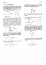
7-20.
Normal operating
voltages
wrthin
the
DC
Ampli-
fier are
shown
on the
schematic
diagram, Figure 7-30.
To
check
the operation
of
various
stages
of
the
amplifier,
hrst
set
the
Sample Rate
control
to
HOLD
and disconnect
the
Bootstrap
Amplif-ier
(white
jumper
wire,
labeled
"Bootstrap"
on
the Al
Component Loca-