


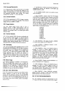
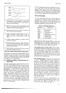

REIUOTE
ENAELE
PROGRAI\,I
LINES
PROGRAM
EXECUTE
PROGRAM
349A.4-2936
lttltl
rtllll
lrrttll
II T2 T3
T4 15
T6 T7
Tl
-
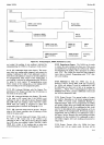
Remote
Enable must
be held
LOW
to
permit
remote
programming.
For reliable
operation,
T1
should
occur
first. lf Remote Enable
goes
HIGH,
program
capability
reverts to
front
panel
controls.
T2
-
Selection of range
and f
unction
programming.
Input
lines
are
HIGH
unless forced
LOW
at Remote
lnput
connector. T1
and T2
may
be simultaneous.
T3
-
Program
Execute
level
must
be LOW
for
a minimum
of
5
ms. T2 and
T3 may
be simultaneous.
T4
-
Program
Flag initiates
ourguard-to-inguard
transfer
of
program
information,
Interval
between
T3
and T4
depends
upon
point
in
scan
sequence
at
which
T3
occurs.
T5
-
Transfer
of
program
information
is complete.
Exrernar
Encode may
be applied.
T6
-
Program
lines
may
be returned
to
HIGH,
if
desired,
at
any
time
after
Program
Flag
goes
LOW.
Any
program
line need
not
be
returned
to HIGH
unless
required
by a
subsequent
program
change.
T7
-Program
Execute
must return
to
HIGH before
a subse-
quent program
change
can
be made.
Model
34904
Section
III
3-89.
The
operating
instructions
contained
in
this
sec-
tion include
address
codes
and
address
code
selection,
program
codes,
output
format,
and
timing
sequence
information.
The
GPIB system
uses
the
ASCII
(Ameri-
can
Standard
Code
for Information
Interchange)
eight-
bit
octal
code
in
a
parallel
bit, serial
character
form.
3-90.
GPIB
BusSignals.
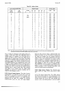
3-91.
For
convenience
and brevity,
each
bus signal
line
is
identified
by a
mnemonic,
which is
an abbreviation
of
the
signal
name.
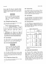
Table
3-5
lists the signals
used
on
the
GPIB
bus.
An
H
preceding
a mnemonic
indicates
that
the
signal
is HIGH
true,
L
indicates
LOW is
true.
Table
3-5.
GPIB
Signal
Mnemonics.
Mnemonic
Signal Name
DAC
DAV
Dro
(1€)
EOP
MRE
REN
RFD
sRo
Data
Accepred
Data
Valid
Data
lnput/Output
End
Output
Multiple
Response
Enable
Remote
Enable
Ready
For
Data
Service Request
Figure
3-6.
Remote
Program
Sequence
(Option
022).
will
maintain
all
normal-
and common.mode
rejection
characteristics
with
the
Remote
Control
lines properly
connected.
Outguard ground
is
isolated
from inguard
common
and
from
chassis
(power
line) ground
and r-nay
be
floated
up
to
40
V
above
chassis.
3-87.
GENERAL
PURPOSE
INTERFACE
BUS I/O
(0ption
030).
3.-88
_The
General
Purpose
Interface
Bus
I/O
option
for
the
Model
3490A
Digital
Voltmeter
allows
the instru_
ment
to
be
controlled
remotely
and to
output
measure_
ment
information
to
a digital
recorder.
It
peimits
remote
programming
of
range,
function,
trigger
mode,
and
Sample/Hold
mode.
Neither
the poweiline
switch
nor
the
Ratio
mode
can
be programmed
remotely.
The
output
data
includes
measurement
status,
function,
polarity,
magnitude,
and
range,
in the
forrnat given
in
Paragaph
3-126.
Several
instiuments
may be connected
in parallel
to
the
same
bus
and
controlied
by
a
sinsle
controlling
insrrumenr.
Controlling
instruments
thlat
may
be
used
with
the
34904
GpIB
option
include
the
-hp
9800
series
calculators
and the
_hp_
Model
32604
\larked
Card
Progammer.
3-92.
Data
Lines
DlOl
through
DlOg.
All eight
Data
Input/Output
lines
are
LOW
true,
as indicated
by
the
L
at the
beginning
of
the
mnemonic. (LOW
=
logical
..1".)
In
the
3490A,
DIO8
is
always
HIGH,
or
logical
..0".
3-93.
Multiple
Response
Enable,
MRE. When
the
Multi_
ple
Response
Enable
line
is
LOW,
all units
connected
to
the
bus
must
respond
to the
controller
and interpret
the
data
on
lines
DIOI
through
DIOT
as
an
adäress
or
command.
When
MRE
is HIGH,
only
the
unit
which
has
been
addressed
as the
talker
and the
unit
(or
units)
addressed
as listener(s)
may
and
are
required
to
respond
0n
the
DAV,
DAC,
and
RFD lines.
'"'
3-94.
Handshake
Signals.
Three
lines
are used
for
what
is called
a
"Handshaking"
technique.
The
listener
(or
listeners)
set
RFD
to
HIGH
to
indicate
readiness
to
accept
data.
The
RFD
line
is
wire
OR'd to
all
units
on
the
bus
so
that
data
will
not
be transmitted
until
the
slowest
listener
on
the
bus signals
that
it
is
ready
for
data.
When
all
listeners
are
ready
(RFD
goes
HIGH),
the
talker
puts
the
first
character
on the
dattlines,
DIOI
_
g.
When
the
data
is
valid,
the
talker
sets
DAV
to
LOW.
As
each
listener
receives
and
has
completed
processing
this
data,
it
allows
its
DAC
output
to
go
HIGH.
This
line is
also
wire
OR'd to
each
unit,
and
the line
does
not
actually go
HIGH
until
all
listeners
have
accepted
the
data.
The
talker
may
not
change
the
data
on
DIOI
_
g
untilDAC
goes
HIGH.
3-95.
RFD. Each
listener
may
set
RFD
HIGH
as
soon
as it
has completed
and
acknowledged
acceptance
of the
previous
data.
This
signals
to
the talker
that
it
mav
transmit
new
data
on
the
data lines
DIOI
-
g.
3-1