


Section
IV
circuit
fumishes
the positive reference
which
is used in
negative
dc voltage
measurements.
A feedback
circuit
which senses the reference
voltage
at
the FET
switch
input to the DC
Amplifier
ensures
the correct
voltage at
that point,
even
though
there
may be switch
and
connector
contact
resistance
in
the circuit.
The input to
the
Inverting
Amplifier, which supplies the
-
Reference,
is also connected
to the sense
point.
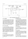
4-1 20.
Plus
Reference.
The
differential
amplifier of this
supply is referenced
to
a
zener
diode which is
in
the
emitter circuit of a feedback
amplifier transistor.
The
diode
and
transistor
are in the
same package,
for
improved
temperature
stability.
The amplifier
gain
is
adjusted
to
provide
an accurate
+
l0 V output.
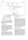
4-1
21.
Minus
Reference. The
-
reference, used
in ac and
positive
dc measurements,
is supplied
by an inverting
amplifier whose
input
is the
+
10
V reference.
The
gain
of this amplifier is
adjusted to
provide
an accurate
-
l0
V
output.
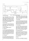
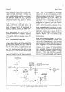
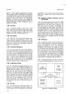
4-122. Ratio Measrements
(0ption
080).
4-123. A
34904 equipped
with
Option
080
is capable
of making
dc-to-dc
and ac-to-dc ratio
measurements.
The
External Reference
Amplifier has
a
gain
of l0
when
the
Ratio switch
is set to the
I V
range. This is necessary to
make
the
external
reference
compatible
with the
refer-
ence
switching
logic, since
in voltage
measurements
*
and
-
l0
V
references
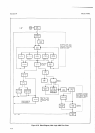
are used. Figure
4-14 is
a
simpli-
fied diagram
of the external
reference amplifier
circuits.
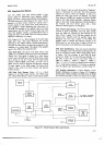
4-124. Extetnal
Reference Amplifier.
A microcircuit
operational
amplifier, connected
in the non-inverting
Model 3490A
mode, is used
as
a buffer
amplifier
for
the
external
reference input.
The
gain
of
this
amplifier
is
selected
by
adjusting the
output of the Feedback Amplifier. A third
microcircuit
amplifier provides current to compensate
for
bias current
drawn
by
the
input
amplifier.
The
External
Reference
Amplifier
input is clamped
to
approximately !
14
V
to protect
against
excessive
input
voltage up to
+
250 V. Greater
input
voltages
may
damage either the protection
circuit or the Reference
Amplifier.
The
amplifier
output
is limited to
approxi-
mately t 14
V for the
protection
of
subsequent circuits.
4-125. Feedback
Amplifier.
An
amplifier
is used in
the
feedback
circuit so
that the External Reference
Ampli-
fier
gain
on the 10
V Ext. Ref. range can
be adjusted
slightly
above or
below unity as required. On the I
V
Ext.
Ref. range, the feedback is
attenuated
to give
the
Reference Amplifier
a
gain
of
10,
because in ratio
measurements, this
reference is substituted for the l0
V
intemal reference.
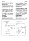
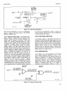
4-126. Input
Compensation Amplifier.
Bias current
at
the input of the External
Reference Amplifier
could
cause
an
offset voltage drop
across
the
input
protection
resistor
if this current
were not compensated
for by the
Input
Compensation Amplifier. Figure 4-15 shows
how
this is
accomplished.
The External
Reference
Amplifier
maintains both
its
inputs
at approximately the same
voltage, so that
the voltage
at
the
inverting
(feedback)
input is essentially equal
to the External
Reference
input.
This voltage is connected to the non-inverting
input of the input
Compensation Amplifier, U2,
which
has
a
gain
of
l. The
output of
U2,
then, is essentially
equal
to
the External Reference input voltage,
and may
be
r
0.1
V to
+
12 V. The amplifier
offset is
adjusted
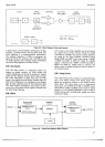
INPUT
PROTECTION
+ I7V
EXTERNAL
REFERENCE
AMPLIFIER
INPUT
COMPENSATION
AMPLIFIER
Figure
4-14.
Simplified Diagram,
External
Reference
Circuits.