


, , iliii#;, ,i
;_r;;rs6tl
I f4Fiü!t{#l tttta
'vvv::ttt:
*iii,tif6l:..it@i6
tigl:,ii
.14,iä,
:*,rii'.i
"-*"rti,"r";
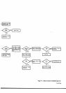
preent?
'_:
i
Check
conriection'
wire)
b۟en
46 at
Troubl6h@t
Filter.
Circuit.
See Note
4.
NO
ä
i
ffi ##'.r,.rllt{i+WQrr,..',,:,.
;
:r,,,,tjjf*-ilsss8iiii..r,
.
.ffi,
t,?rS
lI*
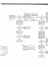
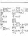
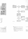
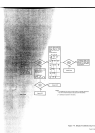
NOTES:
1. DC vollmeter
circuits,
including
logic, must
be
oFraling correctly
betore this
procedure
is
attempted.
2. An
ac €librator,
an oscillos@F, and
a
dc voltmeter
are required for these
cnecKs.
3.
The time
shown on
waveforms is @rrect for
instruments designed
fd
60
Hz
line operation.
For
50 Hz instruments, incrEse time
shown by 20%.
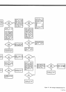
4. Afler repairing
the AC
Converter.
check the owrload
protedion
circuits in the
following
mnner:
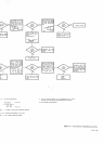
a.
Set 34904 FUNCTION to
AC,
RANGE
ro 1 V,
SAMPLE
RATE ro FAST,
b. Apply
inpur of'10 V at
100
Hz.
c. Moniroi A6TP1
r
d.
lf
Fw{sm
;s
A6Rt4, t5.
e. M6ue rclEg! i
f. lf 6lbgabrcr(
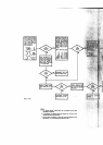
Ser
FUNCTION
ro AC.
Apply Iull,range
input
at
100 H2 on each
range.
Monitor
convener
output
at white wire.
Should be
+1V 10.002Vforfull-
ßnge Input on each
range,
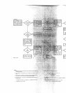
High
lmpedane
Assy.
montto. pin
18
ol
as
AC
Converter
out-
+l
v
r0.002v
for
ange
input.
Troubleshoot
A6 reed
re.
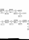
Select 1
V range and
apply
input
ol 1 V at 100H2.
Monilor
iignal at white
wire connected to lower
end of A6Kl with
s@pe.
Should
be the sme as in-
put
signal at
top end of
A6K1
Apply
Iull-range
inpul
al
10OHz
on
@ch range
nitor A6TP2
g,#h
Troubleshoot
46Kl and
driver
circuil.
See
Note
4.