


Model3490A
the same data
lines.
For
this reason a
standard
cable
(which may be
various
lengths)
is used to
connect
each
instrument
to
the bus.
The cable contains
eight
data
lines and
seven
control
lines.
4201. Basic
Theory
of GPIB
l/0
Circuits.
4-202. The
3490A GPIB
circuits employ
two
separate
logic systems
called
Algorithmic
Siate Machines (ASM).
A brief
explanation
of
an
Algorithmic
State
Machine
is
given
in
Parugraph
4-90.
One ASM is
inside
the
instru-
ment
guard (Inguard
State Machine)
and the
other
is
outside
the
guard (Outguard
State Machine).
Each
system must accept,
store,
and
output
information,
providing
a two-way
communication
link
between
the
3490A internal logic circuits
and
the
other
bus
system
instruments. The two
State Machines
are timed
by
separate free-running clocks;
consequently,
communica-
tion
between
the
two machines
is
asynchronous.
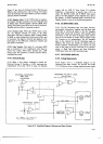
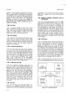
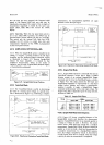
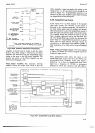
Figure
736 is a block
diagram of the
GPIB
I/O
circuits.
Table
3-5 lists
the bus signal mnemonics.
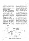
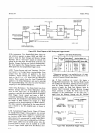
4-203. Information
is transferred
across
guard
from
one
ASM
to the
other
by means
of
photo-transistors,
so that
there is no
electrical
contact
between
inzuard
and
outguard circuits.
This
allows the
inguard
anä'outguard
circuits to
operate
on
different
ground
systems
at
different potentials.
The
outguard
ASM
receives
and
interprets
information
from the
controller.
It then
responds
to
the
controller,
and
transfers
the
necessary
information
across
guard
to the
inguard
ASM,
which
programs
the
3490A
logic
circuits.
When
the instrument
is
addressed
to
talk,
the
measurement
output
data is
transferred
across guard
one
digit
or
character
at
a
time.
P11u
Ir then
placed
on
the
bus
data lines
DIOI
through
DI07
one character
at
a
time
in
the
sequence
shown in
Paragaph
3-126.
Tlre
timing
of the
data output
is
controlled
by
the
three
"handshake"
sigrals
described
in
Paragraphs
3-94
through
3-97.
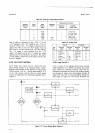
4-204.
GPIB
System
Operation.
4-2-O!.
Reset.
When
power
is
first
applied to
the
3490A,
the
Reset
circuit
output
is
LOW
for
approxi-
mately
100
ms.
This
sets
the
inguard
ASM to the-,izero,'
state,.and
sets
the
range
and function
circuits
to
the
front
panel
settings.
It
also
clears
the
Sample/Hold
and
Remote
storage
flip-flops
and the
trigger
mode, causing
all
programming
to
conform
to
the
fiönt panel
settingsl
The
outguard
ASM
circuits
then
check
io
see if the
3490A
logic
circuits
indicate
that
the
instrument
is in
remote
control.
If
not,
the
instrument
continues
to
be
controlled
from
the
front
panel.
+246.
Local
Control.
In
local
control,
the
I/O
circuits
accept
and store
range
and
function
information
from
the
front
panel.
Sample
Rate
and
Sample/Hold
(option_
al)
are controlled
from
the
front
panel.-This
information
may
be updated
at
any
time
by changing
the
control
s€ttings.
If
the
Sample
Rate
control
ls set to
HOLD, the
Section
IV
3490A
may
be triggered
through
the
rear panel
Trigger
connector.
If
addressed
to
talk,
the
3490A
will
output
measurement
data
in
accordance
with
normal
bus
operation.
4-2O7.
Address
to
Listen.
When
the
Outguard
State
Machine
senses
that
the
MRE
line is
LOW,
it
waits
for
DAV
to go
LOW
indicating
that
the
data
information
is
valid.
When
LDAV
is
received,
data lines
DI05
through
DIOI
are
compared
to
the
34904
address
bits. If
thöv
match,
DI07
is
checked
to
determine
if
the
address
is
tä
talk
or to
listen.
If
DI07
is
HIGH,
the
3490A
is
addressed
to
listen.
It then
checks
REN
to
see
if
it
is
LOW.
If
so,
the
internal
RMT
line
is
set
LOW
and this
information
is transferred
across guard
and
the
Inguard
State
Machine
sets
the
3490A
to
remote
control,
disabling
the
front
panel
range,
function,
and
Samplef
Hold
controls.
As soon
as
the
address
data
and
tn,
fiBN
line
have
been
checked,
the
DAC
output
is
allowed
to go
HIGH,
indicating
that
the
data has
been
accepted.
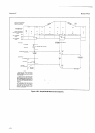
4-208.
Remote
Programming.
After
the
3490A
has
been
instructed
to
listen
and placed
in
remote
control.
the
controller
sets
MRE
High so
that
the
3490A
can
receive
remote
program
data. This
data is placed
on the
seven
data lines
DI0l
-7
by
the
controller,
one
character
at
a time.
After
each
character
is placed
on the
data
lines,
the
controller
sets
DAV
to
LOW, indicating
to
the
349OA
Outguard
State Machine
that
this
data iJ
readv.
The
Outguard
State
Machine
checks
to
see if
the
datals
valid
for the
3490A
and
then
transfers
the
data
across
guard
to the
Inguard
State Machine.
It
also sets
the DAC
line
HIGH
and
RFD
LOW to
indicate
that
the
data
has
99rl
accepted
and
is
being processed.
The
Inguard
State
Machine
then
interprets
the
data
and takes
appropriate
action.
For
example,
if
the
character
received
is
the
alpha
identifier
R, the
inguard
circuits
are set
so that
the
next
character
(if
it
is
a
digit) is
routed
to
the
ranse
storage
circuit. (See
Paragraph
3-106
for
the
..rnol.
programming
sequence.)
After
a data
character
has
been
'
'i
processed,
RFD
is
allowed to go
HIGH,
ind"icating
to
the
iL
controller
that
the
3490A
is
ready for
new
data.
4-209.
When
programming
is completed,
the
controller
must
send
the
ASCII
code
character
E,
after
which
it
may
address
the
34904
to
talk
or it
may
address
anv
other
unit
on
the
bus to
listen
or talk.
The
character
6
indicates
to
the
3490A
that
the progamming
is
ended.
The 3490A
then
will
not
accept
any
more
data until
after
MRE
has
again
been
set
LOW
and
the
3490A
listen
address
sent.
4-210.
Address
to
Talk. When
the 3490A
is
addressed
to
talk,
it
outputs
the
measurement
data in
the
format
shown
in
Paragraph
3-126.
The
output
sequence
is
controlled
by the
Inguard
State
Machine
tlirough
a
multiplexer
and
a storage
unit.
As each
output
data
character
is transferred
across guard,
the
öutguard
circuits
place
this
character
on
the
data
lines
and set
DAV
to
LOW,
indicating
to
the
listener
that
valid
data is
available.
When
the
listener
sets
DAC
HIGH,
indicating
+2r