


Section V
b.
Connect
the battery
to
IMUT
terminals,
*
to
HIGH,
-
to
LOW.
Note
and
record
3490A display.
c.
Connect
dc
standard
to
EXT
REF
terminals
and
set
standard
output
to
positive voltage equal to display
noted
in step b.
d.
SET
490A
RATIO
switch to EXT REF l0 V.
Display should be
+
09.9982
to
+
10.0018.
e.
Reverse
polarity of dc standard output. Display
should be
-09.9982
to
-
10.0018.
f.
Set
RATIO
switch
to INT
REF. Reverse
polarity
ofbattery
connections.
Note
and record
display.
C.
Set
RATIO switch
to EXT
REF 10V. Adjust dc
standard
output
to negative voltage equal to display
noted in
step f. Dsplay should now be
+O9.9982
to
+
10.0018.
h.
Reverse
polarity
of dc standard output. Display
should be
-O9.9982
to
-
10.0018.
i. Reduce dc standard output
to 1/10 the output
used in step h.
j.
Set
RATIO switch to EXT
REF lV.
Display
should
be
-09.9982
to
-
10.0018.
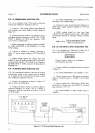
S41.
AC/DC
Ratio Accuracy Test.
5-42. A
dc standard
(hp-
7a0B) and an ac calibrator
(hp-7a5A)
are required for
this test.
r...
a. Set 3490A
RATIO
switch to EXT REF I V.
Connect dc standard
to
EXT REF terminals
and adiust
standard
output to
+
0.10000 V.
b.
Set 3490A FUNCTION
to
AC,
RANGE
to I V.
Connect
ac calibrator to IMUT terminals and adjust
calibrator
output to l00mV
at
l00Hz. Display should
be
0.99865 to
I
.00135.
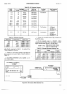
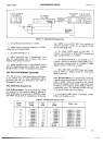
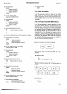
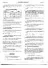
c.
Select EXT
REF
and
INPUT
ranges and
voltages
listed in
Table
5-8.
Display should
be as
indicated in
each case.
Model
34904
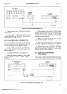
5-43.
External Reference
Input Resistance
Test.
544.
L dc
standard
Chp-
7a0B)
and a l0k9"tO.l%
resistor
(-hp-
0698a157\ are
required
for this test.
a. Set
34904 RATIO
switch to
EXT REF
l0 V.
FUNCTION
to DC, RANGE
to
l0
V.
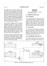
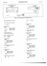
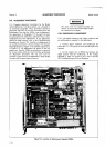
b.
Connect 3490A.
dc standard and
l0 k,f)
resistor as
shown in Figure 5-8. Connect
jumper
across
resistor.
c. Adjust dc
standard output
to
+
10.0000
V. Note
34904
display.
d. Remove
jumper
across resistor.
Display should not
change more
than 100 counts, verifying an
EXT REF
input resistance
of
)
l0?
Q.
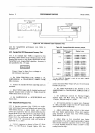
5-45.
GPIB 0PEBATIONAL
CHECK
(0ption
030).
546. A General
Purpose
Interface Bus system controller
and a
printer
are
required
to verify
the
operation
of the
3490A
Option 030.
Two
procedures are
given. The
first,
in Paragraph 547,is a
general procedure to
be
used with
any bus
controller.
The second, in
Paragraph 5-49, is
essentially
the same
procedure
written
specifically for
the
9820A
calculator.
If
the
3490A
I/o
circuits fail
to
operate
correctly,
refer to the GPIB
troubleshooting
information, P
ar agr aph
7 49 .
l.
Initialize
LEOP
-
Set
End
Output
[.ow
HEOP
-
Return End Output
to iligh
LREN
-
Set
Remote Enable LOW
2. Send addresses
(see
Paragraph 3-104
for 3490A
address codes)
LMRE
Set
Multiple Response Enable LOW
?
(77
s)
-
Universal unlisten command
6
(668)
-
3490A listen address
(3490A placed
in re-
mote mode)
HMRE
-
Set Multiple
Response Enable HIGH
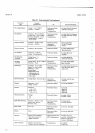
programming
instructions
Test
No. I
PERFORMANCE CHECKS
3.
Send
i)
rJ
Table 5-8.
AC/DC Ratio
Accurary
Test'
Ext
Ref
Range
Ext
Ref
Voltage
I nput
Range
lnput
Voltage
Display
Limits
iV
1V
1V
10v
10v
10v
10v
0.50000
v
1.00000
v
1.20000
v
1.00000
v
5.00000
v
10.ooo0
v
12.0000
v
1V
1V
1V
10v
10v
10v
10v
0.50000
v
1.00000
v
1.00000
v
1.00000
v
5.00000
v
10.0000
v
10.0000
v
0.99865
to
1 .00135
0.99865
to 1.00135
0.83218 to
0.8348
09.9865
to 10.0135
09.9865
to 10.0135
09.9865
to 10.0135
08.3218 to 08.3448
5€