


Model3490A
7.77.
LOGIC
GATE
SYMBOLS.
7
-78.
L
humber
of
logic
gate integrated
circuits
are used
in the
3490A.
Most of
these are
TTL
circuits,
in which
the HIGH
logic
level is
2+
2.4
V and
LOW
is
(r
0'5 V.
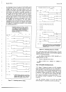
The
normal
symbol
used to
indicate
a 2-input
NAND
Gate
is shown
below, accompanied
by
the truth
table.
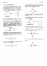
NAND GATE
Truth
Table
ABC
CLLH
HLH
LHH
HHL
As the
truth table
indicates, both
inputs
must be
HIGH
(true)
to
obtain a LOW output.
The
purpose ofthe
circle
(invert
symbol) at the
gate output
might
then
be
assumed
to indicate that the
signal
is LOW
true at
that
point. The
truth statement for
this
NAND
Gate
may be
restated
to read,
"A
LOW
signal at
either
input results
in
a
HIGH output,"
and the
same
truth
table applies.
In
keeping
with this statement
and
the use
of the
circle to
indicate a LOW
true
sigtal, the following
"OR"
function
symbol
may be used.
In
some
cases, a
NAND Gate
circuit may
be used
to
invert a
logic signal.
This may
be done by
connecting
the
same sigral
to both
inputs.
If this is done,
the
following
symbol may be
used,
indicating
that the
circuit merely
inverts the
sienal.
If
the input sigral
is
LOW
true,
the circle may
be
placed
on
the input
side of the
symbol.
Section VII
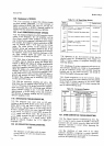
The NAND
Gate
may
also
be
used as
an
inverter by
connecting one input
permanently to HIGH
(+
5
V).
In
this case, the circuit may be
shown as
follows.
Note
that the same truth
table
applies,
and that if one
input
is
held HIGH,
the
output
is the inverse of
the
other
input.
7-76.
Another
gate
circuit
used is the
Exclusive
OR
Gate,
normally
drawn:
A
A
Exclusive
OR Gate
Truth Table
ABC
LLL
HLH
LHH
HHL
Note
from
the truth table that the output is HIGH if
one,
and only one,
input
is
HIGH.
When both inputs
are
either HIGH or LOW,
the
output
is LOW.
If
one input
is
held LOW
(connected
to
ground,
for
example)
at all
times, the
output
follows the other
input. When used in
this manner, this symbol may be used.
If
one
input is held HIGH
(+
5 V),
an
inverter symbol
-,
may bg
used, because
the output
becomes
the
inverse
of
the input.
+5V
+5V
7-9