


Section IV
returns
to
LOW
to indicate
programming
is
complete.
While the signal is HIGH,
it enables
gates
in
both inguard
and
outguard circuits
to
allow
transfer
of
information.
At the same time, an
output from the
Sequential
l,ogic
disables the
State
Clock
signal to
the
t-ocal/Remote
Flip-Flop, to
prevent
the clock
from
changing
the
flip-flop during
a remote
programming
period,
When the
Program Flag
signal is
LOW, it
disables
the
Scan
A
divide-by-two flip-fl
op.
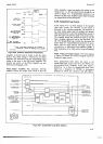
4186.
Data Clock.
+187.
A Frequency Doubler is used
so that
a clock
pulse is issued for each transition
of
the
Scan
A
signal.
These
clock
pulses
are delayed slightly
before being
applied
to
the
Shift Registers, to
allow time
for the
program
information to
reach
the proper
state.
+188. Shift
Registers.
+189.
One-half of the
dual 4-bit shift register
micro-
circuit
carries
the
range
information,
and the
other
contains function
information.
Each Data
Clock
pulse
shifts the information
bits in the
registers one
position
and inserts
a
new
bit.
The shift
register
outputs
are
applied to two
multiplexers.
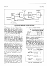
41 90.
Local/Remote
Multiplexers.
+191 . The
four outputs
from each of these
multiplex-
ers may be either
of two
sets of four inputs.
One
set
of
four inputs is the
remote program
information
bits, and
the
other
set
is the
corresponding
information
from the
front
panel
switches.
The logic level
of the
"output
select"
connection
to the
multiplexer selects
either
{he
local
or remote program
information.
The
"outpüi
select"
signal
is the
output of the
Local/Remote
Flip-Flop.
The
multiplexer
outputs are the
range
and
function information
used in
the
logic
circuits.
4-1
92. LocaURemote
Flip-Flop.
4-193. The
Local/Remote
Flip-Flop provides
the
"out-
put
select"
signal
to the
Incal/Remote
Multiplexers.
A
NOR
gate
is
used to gate the
State Clock input to
the
flip-flop.
When
the
3490A
is
turned
on,
the
Turn-on
L
signal
from the
logic
circuits sets the
Local/Remote
Flip-Flop
to
the
local
state.
When
the
Remote Enable
line
at the
rear
panel
connector
is held
LOW,
a
L,OW
sigtal
is
applied
to the
D input of the
flip-flop.
A HIGH
State Clock pulse
then
sets
the
Q
output
LOW. This
LOW signal
to
the
multiplexers selects the
remote
program
information.
An
inverter
connected
to
the
other flip-flop
output
drives
the
Remote
annunciator in
the
display.
4194. Dau
Flag.
t195.
The
Data
Flag
output signal goes
HIGH
at the
begrnning
of a
measurement
and
LOW
to indicate
the
reading sequence
has
been
completed.
If the
instrument
+10
Model3490A
is operating
in
the
autorange
mode, Data
Flag
remains
HIGH until
a
reading on
the
correct
range
has
been
completed.
4.196.
GENERAL
PURPOSE
INTERFACE
BUS
I/O
(0PTtoN
030).
4-197.
The
General Purpose
Interface Bus I/O
(GPIB)
option permits
the
Model 3490A
to
operate
on
a
single
data/control
bus with several other instruments.
The
ASCII code,
used in this system, is
an
eight-bif
+2-l
octal code,
parallel
bit,
serial character. The 3490A I/O
has
a
talk
address
and a
listen
address, which allows
the
controlling instrument
to
instruct
the 3490A to
output
measurement
data or to receive
programming
informa-
tion.
Since each
instrument
on the bus may
have
its
own
distinct address codes,
a
single controller is
able to
instruct
or receive
data from each one
individually.
The
3490A
GPIB option is compatible with the
-hp-
9800
series calculators.
4-198.
GPIB
System.
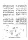
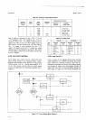
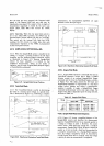
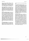
4-199.
A typical
bus
system is shown in Figure
4-20. A
total
of 15 instruments
may be
connected
in
parallel
to
the
bus. Each instrument
on
the
bus
is
assigred an
address
(or
addresses) so that it can
be selected
individually
by
the controller. This enables the control-
ler to
determine which
instruments
will
be
communica-
ting
on
the
bus at
ury
given
time. An
instrument
will
have
a
listen
address
if
it
can
receive
data, a
talk
address
if it
can output data, or
both a
listen
and
a
talk
address
if it
can both receive and transmit
data.
For
example,
the listen
address for
the
3490A
is
normally the
ASCII
code character
6, and
the normal talk
address
is
V,
assigned as shown
in Paragraph
3-104.
and
Table
3-6.
4-200.
A
principal
advantage of the bus system is that
both remote
programming
and data output are done on
9820A
CALCULATOR
(CONTROLLER}
3490A
DVM
(TALKE
R}
(LISTENERI
FREOUENCY
COUNTER
(TALKER}
(LISTENERI
PR
INTE
R
(LISTENER}
12
ft. MAX.
ASCII
8US
CABLES
Figure
4-20.
Typical Bus System.