


Model3490A
Section
III
SECTION III
OPERATING
INSTRUCTIONS
3-1.
INTR0DUCTI0N.
3-2.
This
section
contains
instructions
for using
the
Model
34904
Multimeter
to make dc
voltage, ac voltage
and
resistance
measurements.
It
also
includes
instruc-
tions
for
sample/hold
and ratio
measurements, remote
control
and
data
output.
Basic operating
instructions
may
be
found
on
a
pull-out card at
the
bottom edge
of
the
3490A
front
Panel.
3.3.
INSTBUMENT
CAPABI
LITIES.
3-4.
Standard
I nstrument.
3-5.
The
standard
Model
3490A Multimeter
makes dc
voltage,
ac
voltage
and resistance
measurements with
S-digit resolution
and
up
to I 20
%
of range on all
ranges
except
l000Vac
to
dc.
The
3490A
has five dc
voltage
ranges,
.l
V
to
1000V;
4 ac
voltage ranges,
I V to
1000V; and
six resistance ranges,
I kO to 10,000kQ.
Ranging
may be
manual
or automatic. Polarity
selection
and display
are
automatic.
A self-test feature is included
which
checks
certain operations within
the instrument.
3-6. Output
and Remote Gontrol 0ptions.
3-7.
Data
Output
Option
021
and Remote
Control
Option
022. Option 021
provides
ten
columns of
binary
coded decimal
(BCD)
output data.
This
data
may be
either HIGH true or LOW true,
as selected by
a
slide
switch
on
the
outguard data output
printed circuit
assembly. With
Option
O22, the
349OA
range
and
function may be
programmed
by LOW
true
input
information.
External
triggering
is
possible
with
either
option.
3-8. General Purpose
Interface
Bus ll0
Option
030. The
General Purpose
Interface
Bus I/O
(GPIB)
option
permits
remote
programmhg
and data
output on
the same
bus lines. The 3490A
may be
connected
to
a
bus in parallel
with several
other
instruments and
controlled
by
a single
controlling instrument.
Remote
control
of range,
function,
trigger mode and sample/hold
mode
is
possible
with
Option 030.
The output data
includes
measurement
status,
function,
polarity, magni-
tude
and range,
in the
format
given
in Paragraph
3-126.
Controlling
instruments
that may be used with the
3490A
GPIB option
include
the
-hp-
9800A
series
calculators
and
the
-hp-
Model 3260A
Marked Card
Programmer.
3-9.
Sample/Hold
0ption
040
or
045.
3-10.
The
Sample/Hold
Option
(040
or
045)
enables
the
\todel 3-190.{
Multimeter
to sample
a
changing input
voltage
and hold
that
sample
long enough to measure its
amplitude. This
permits pulse
height measurements and
digitization of
changing
waveforms
such
as ramps or
sine
waves.
The
extemal
trigger circuits are
isolated
from the
signal input Low terminal and from chassis
ground,
which allows the voltmeter
to
make
guarded
floating
measurements. The
designations
used for the
34904
Sample/Hold options are as
follows:
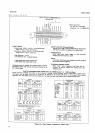
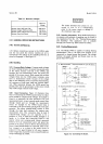
When Sample/Hold
is
installed
The
Sample/Hold
option
in a 3490A with:
is designated as:
BCDiRemote
Expand
Option 020
Option 040
GPIB
Option
030
Option
040
Neither 020 or
030
Option 045
3-11. Batio
0ption
080.
3-12.
The 3490A
equipped with Ratio Option
080
is
capable of making three-wire dc-to-dc
or
ac-to-dc ratio
measurement. Two External Reference ranges are pro-
vided, the
I
V
range accepting reference
voltages of
10.1
V to
t 1.2V,
and
the 10V
range accepting
voltages from
t
I
V
to
t
12V.
3.13.
FRONT AND
REAR
PANEL
OESCRIPTION.
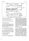
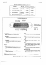
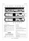
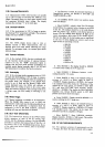
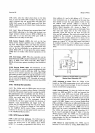
3-14. Figure 3-l
shows the front and rear
panel
controls
and connectors
and
gives
a brief
description
of each.
Some of the features shown
are available
onlv
with
certain options.
,.
3-15.
MAXIMUM INPUT
VOLTAGES.
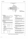
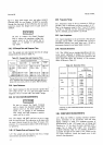
3-l 6.
Table 3-l
lists
the
maximum allowable voltages
between
input terminals,
and between the
terminals
and
chassis. These maximum
voltages are
also
shown
on the
front
panel
and
must
not be exceeded or
damage
to the
instrument
may
resull.
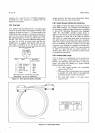
wAR]ililG
If the
34904 has a rear
input connector,
the
front
and rear terminals are
internally
connected
in
puallel.
If
high
voltages may
be applied, always
protect
the open
termi-
nals. Be
ilre
the rear input
terminals
are
open
before connecting
an
input to
the
front
terminals
and vice
versa.
3-l