


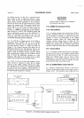

TEST OSCILLATOR
hp 652A
,,' \ l/-.----\l
(o)@L
'e
\- /
@'\--O
@
-
@
oo
M
ULTIMETER
hp
349OA
34904-A-?947
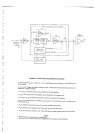
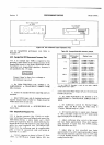
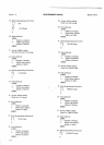
Figure
5-6. AC
Voltmeter Input lmpedance
Test.
Section V
PERFORMANCE
CHECKS
Model
3490A
with the
Sample/Hold performance
tests.
Refer
to
Paragraph
5-9.
$32. Sample/Hold
BC Mea$rement
Aecuracy
Test.
5-33. A
dc
standard
(-hp-
7a0B) is
required for this
procedure,
which checks
the
dc voltage
accuracy
of
the
Sample/Hold circuits
to
the
90-day specification
in
both
Track/Hold
and Acquire/Hold
operation.
Accuracy is
not
specified
for the
.l V range.
Connect
Guard
to
Input
Low
or damage to
the instrument
mav result.
a.
Set
3490A
FUNCTION
to
DC,
RANGE
to
I V,
SAMPLE/HOLD
to
TRACK/HOLD,
SAMPLE
RAT.A,
fully
clockwise.
b.
Connect
dc standard
between
input
High
and
Low
terminals.
c.
Select
3490A
ranges
and
dc standard positive
and
negative
outputs
listed in
Table
5-6.
Display
should
be
within
limits
shown
in each
case.
d.
Set
SAMPLE/HOLD
to ACQUIRE/HOLD
and
repeat
step
c.
$34.
Sample/Hold
Response Test.
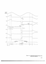
5-35.
A function
generator (-hp-
3310A),
an oscillo-
scope
with
delayed
sweep
and delayed
gate
output
(-hp
l80C/l80lAll82lA),
a silicon
diode, and
a l0kh
resistor
are
required
for
this test,
which
verifies that
the
Sample/Hold
circuits
will
respond
to a step
input
voltage
within
the
stated
acquisition
time.
The Delayed
Gate
Output
from
the
oscilloscope
must
be a negative-going
pulse
at
least
30
nanoseconds
wide
and havins
an
amphtude
of
I
to
100
V.
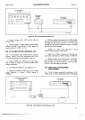
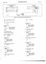
f,.
Conne''r
equipment
as
shown
in Figure
5-7. If the
-r490A
ha:
BCD
Remote
Expand
Option
020, also
i+
*
lf
-hp-
74OB DC
Standard
is
used,
do
not
apply negative
\roltage
greater
than
-
5OO
V.
connäct
Stretched
Pulse
Output
(J7
pin
l0)
to
External
Enclode
(J7
pin
28).
b.
SEt
3490A FUNCTION
tO DC,
RANGE
tO
IO
V,
SAMPLE/HOLD to TRACK/HOLD,
SAMPLE RATE to
HOLD.
c.
Set
oscilloscope
controls
for External
Trigger,
negative
slope, and
Main sweep.
Set
Main
sweep
to
.1
ms/div., Delayed
sweep to I ps/div.
d.
Set function
generator
to square
wave, frequency
to
I
kHz, and
adjust
output
level
for
20 V
peak-to-peak
signal
as
displayed
on
oscilloscope.
e.
Adjust oscilloscope
delay control
so that
intensi-
fied trace
begins
approximately
450
ps
after negative-
going
transition
of square
wave. Note
34904
reading,
which
should be near
zero.
f.
Adjust delay so
that
intensified trace
begins
approximately 125
ps
after
negative-going
edge
of square
wave
(stated
maximum
acquisition
time
for l0
V range
is 128
ps).
Reading should
be within
1
0.001
V of the
reading noted
in step e.
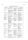
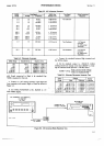
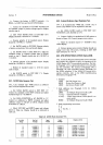
Table
5-6.
Sample/Hold
DC
Accuracy
Check.
3490A
Range
DC Standard
Output
Display Limits
1
V
10v
100 v
1000 v
r
0.10000 V
r
0.50000 v
r
1.00OO0
V
1
1.00000
v
r
5.00000 v
I
10.0000
V
r
l0.0O0O
V
r
50.0000 v
r
100.000
v
1100.000
v
t
500.000
v
'+
1000.oo
v
r
0.0998 to
0.1002
V
!
0.4998 to
0.5002 V
t
03997 to
1.0OO3
V
100998
to
01
.002 V
+
04998 to
05.002
V
!
09.997 to 10.OO3
V
t
009.98 to
010.02 V
t
049.98
ro
05O.O2
V
I
099.97 to
100.03
V
t
0099"8 to
0100.2
V
!
0499.8 to
0500.2
V
r
0999.7 to
1OO0.3
V