


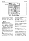

Model3490A
shown
in
Table
l-2
under the
"Time
Response
Chara-
cteristics"
heading. The
shorter the time
between mea-
surement points,
the
greater
the
accuracy of the
recon-
structed waveform
will be.
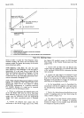
3-176.
Digitizing
a
Sine Wave.
The rules that
apply
when-digitizing
a ramp
@aragraph
3-174)
also apply to
measurement
of
a sine
wave. Keep in mind that
the
dV/dt
and
frequency
limits
given
in Paragraph 3-158
and
Table
3{
must
be
observed.
The waveform
may
be
reconstructed
from
the
Track/Hold
measurement infor-
mation
as
discussed
in Paragraph
3-175.
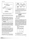
3-177.
Ramp
Linearity
Measurement
Aided by an Oscil-
loscope.
An
oscilloscope
with
delayed sweep and
a
delayed gate
output
can
be very
helpful in making
Sample/Hold
measurements
of a repetitive
waveform.
For
example,
linearity
of a
ramp can be measured
accurately,
as in
the
following
procedure.
a.
Choose
an
oscilloscope
with
delayed
sweep, such
as
the
{rp-
Model
l80C
with
the l82lA
Time
Base/
Delay
Generator
plug-in
unit.
Be
sure the
Delayed Gate
output
from
the
oscilloscope
meets the
Sample/Hold
Tdry:.
input
signal
requirements
given
in
päragraph
3-l
60.
b.
Connect
the
Delayed
Gate output from the
oscilloscope
to
the
S/H
AC
Trigger
input. lf the 3490A
has Option
020
installed,
connect the
S/H
Stretched
Pulse
Output to the External Encode
input
(see
Para-
graph
3-170).
c.
Connect
both the Main Gate
and Delayed
Gate
outputs
from the oscilloscope to
an interval timer
(such
as the
-hp-Model5300Al53O2A)
to
determine the
delay
time
accurately.
d. Connect
the ramp sigral to
be measured
to both
the 3490A
input
and the oscilloscope
vertical
input.
The
slope of the
ramp must
be
within the
limits
given
in
Paragraph 3-158
and
Table 3-8. Trigger
the
oscilloscope
main sweep
at
the
beginning of the
ramp.
e.
Set
the
SampleiHold control to
TrackiHold. The
measurement
will
then be
triggered
at
the point
where
the
delayed-sweep
intensified trace
appears along
the
ramp.
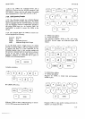
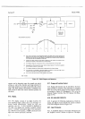
f.
Position
the
delayed-sweep intensified
trace at
any
number
of sampling points (at
least
three)
along
the
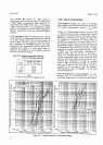
ramp, as shown
in Figure 3-13.
g.
The slope
of
the
ramp
between various measure-
ment
points
can then be compared to
determine
linearity.
ln
Figure
3-13,
for example, slope AB should
be compared
to slope BC
as follows:
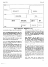
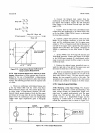
Section III
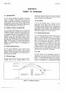
TNPUT
VOLTAGE
AT
TIME
OF
S/H
TRIGGER,
t
/l
/l
VOLTAGE ACTUALLY
MEASURED.
I
I
I
I
Ar
A
T
V
S
=
ANALOG DELAY
=
SAMPLE/HOLD
TRIGGER
(TRACK/HOLD
MODE)
=
VOLTAGE
MEASURED
=
SLOPE, SEE
PARAGRAPH
3-12
FOR
MAXIMUM
SLOPE
PERMISSIBLE.
Figure
3-1 2. Digitizing
a
Ramp.
3-r9